
Boating › OUPV License › Fire Prevention and Firefighting
Fire Prevention and Firefighting
What the Coast Guard lists under this subject
Fire Prevention and Firefighting Appliances
Classes and Chemistry of Fire
Basic Firefighting and Prevention
Fire or Explosion
Verbatim from the National Maritime Center's published examination topics.
§ 181.115 Applicability; preemptive effect.
The regulation, word for word — 46 CFR 181, § 181.115
(a) Except as otherwise required by paragraphs (b) and (c) of this section, an existing vessel must comply with the fire protection equipment regulations applicable to the vessel on March 10, 1996, or, as an alternative, the vessel may comply with the regulations in this part.
(b) An existing vessel with a hull, or a machinery space boundary bulkhead or deck, composed of wood or fiber reinforced plastic, or sheathed on the interior in fiber reinforced plastic, must comply with the requirements of §§ 181.400 and 181.405 of this part.
(c) New installations of fire protection equipment on an existing vessel, which are completed to the satisfaction of the cognizant Officer in Charge, Marine Inspection (OCMI) on or after March 11, 1996, must comply with the regulations of this part. Replacement of existing equipment installed on the vessel prior to March 11, 1996, need not comply with the regulations in this part.
(d) The regulations in this part have preemptive effect over State or local regulations in the same field.
Amendment history: [CGD 85-080, 61 FR 982, Jan. 10, 1996, as amended by USCG-2006-24797, 77 FR 33891, June 7, 2011; USCG-2024-1103, 90 FR 52881, Nov. 24, 2025]
§ 181.120 Equipment installed but not required.
The regulation, word for word — 46 CFR 181, § 181.120
(a) Fire extinguishing equipment installed on a vessel in excess of the requirements of §§ 181.400 and 181.500 must be designed, constructed, installed, and maintained in accordance with a recognized industry standard acceptable to the Commandant (CG-ENG-4).
(b) Use of non-approved fire detection systems may be acceptable as excess equipment provided that—
(1) Components are listed by an independent, nationally recognized testing laboratory as set forth in 29 CFR 1910.7, and are designed, installed, tested, and maintained in accordance with an appropriate industry standard and the manufacturer's specific guidance;
(2) Installation conforms to the requirements of 46 CFR chapter I, subchapter J (Electrical Engineering), especially the hazardous location electrical installation regulations in 46 CFR 111.105; and
(3) Coast Guard plan review is completed for wiring plans.
Amendment history: [USCG-2012-0196, 81 FR 48299, July 22, 2016]
§ 181.300 Fire pumps.
The regulation, word for word — 46 CFR 181, § 181.300
(a) A self priming, power driven fire pump must be installed on each vessel:
(i) Of not more than 19.8 meters (65 feet) in length which is a ferry vessel;
(ii) Of not more than 19.8 meters (65 feet) in length that carries more than 49 passengers; or
(iii) Of more than 19.8 meters (65 feet) in length.
(b) On a vessel of not more than 19.8 meters (65 feet) in length carrying more than 49 passengers, and on a vessel of more than 19.8 meters (65 feet) in length, the minimum capacity of the fire pump must be 189 liters (50 gallons) per minute at a pressure of not less than 414 kPa (60 psi) at the pump outlet. The pump outlet must be fitted with a pressure gauge.
(c) On a ferry vessel of not more than 19.8 meters (65 feet) in length carrying not more than 49 passengers, the minimum capacity of the fire pump must be 38 liters (10 gallons) per minute. The fire pump must be capable of projecting a hose stream from the highest hydrant, through the hose and nozzle required by § 181.320 of this part, a distance of 7.6 meters (25 feet).
(d) A fire pump may be driven by a propulsion engine.
(e) A fire pump must be permanently connected to the fire main and may be connected to the bilge system to meet the requirements of § 182.520 of this chapter.
(f) A fire pump must be capable of both remote operation from the operating station and local operations at the pump.
Amendment history: [CGD 85-080, 61 FR 982, Jan. 10, 1996, as amended at 62 FR 51358, Sept. 30, 1997; USCG-2024-1103, 90 FR 52881, Nov. 24, 2025]
§ 181.310 Fire main and hydrants.
The regulation, word for word — 46 CFR 181, § 181.310
(a) A vessel that has a power driven fire pump must have a sufficient number of fire hydrants to reach any part of the vessel using a single length of firehose.
(b) Piping, valves, and fittings in a fire main system must comply with subpart G, part 182, of this chapter.
(c) Each fire hydrant must have a valve installed to allow the firehose to be removed while the fire main is under pressure.
(d) Spanner wrenches must be provided where a 40 millimeter (1.5 inch) diameter firehose is required by § 181.320(b). Existing vessels as of July 22, 2016 have 180 days to comply with this requirement.
Amendment history: [CGD 85-080, 61 FR 982, Jan. 10, 1996, as amended at 62 FR 51358, Sept. 30, 1997; USCG-2012-0196, 81 FR 48299, July 22, 2016]
§ 181.320 Fire hoses and nozzles.
The regulation, word for word — 46 CFR 181, § 181.320
(a) A fire hose with a nozzle must be attached to each fire hydrant at all times. For fire hydrants located on open decks or cargo decks, where no protection is provided, hoses may be temporarily removed during heavy weather or cargo handling operations, respectively. Hoses so removed must be stored in nearby accessible locations.
(b) On a vessel of not more than 19.8 meters (65 feet) in length carrying more than 49 passengers, and on a vessel of more than 19.8 meters (65 feet) in length, each hose must:
(1) Be lined commercial fire hose that conforms to UL 19 (incorporated by reference, see 46 CFR 175.600) or hose that is listed and labeled by an independent laboratory recognized by the Commandant as being equivalent in performance;
(2) Be 15.25 meters (50 feet) in length and 40 millimeters (1.5 inches) in diameter; and
(3) Have fittings of brass or other suitable corrosion-resistant material that comply with NFPA 1963 (incorporated by reference, see 46 CFR 175.600) or other standard specified by the Commandant.
(c) Each fire hose on a vessel of not more than 19.8 meters (65 feet) in length carrying not more than 49 passengers must:
(1) Comply with paragraphs (b)(1) and (b)(3) of this section or be garden type hose of not less than 16 millimeters (0.625 inches) nominal inside diameter;
(2) Be of one piece not less than 7.6 meters (25 feet) and not more than 15.25 meters (50 feet) in length; and
(3) If of the garden type, be of a good commercial grade constructed of an inner rubber tube, plies of braided fabric reinforcement, and an outer cover of rubber or equivalent material, and of sufficient strength to withstand the maximum pressure that can be produced by the fire pump. All fittings on the hose must be of suitable corrosion-resistant material.
(d) Each nozzle must be of corrosion-resistant material and be capable of being changed between a solid stream and a spray pattern. A nozzle on a vessel of not more than 19.8 meters (65 feet) in length carrying more than 49 passengers, and on a vessel of more than 19.8 meters (65 feet) in length, must:
(1) Be of a type approved in accordance with approval series 162.027; or
(2) Be of a type recognized by the Commandant as being equivalent in performance.
Amendment history: [CGD 85-080, 61 FR 982, Jan. 10, 1996; 61 FR 20557, May 7, 1996; 61 FR 24464, May 15, 1996, as amended at 62 FR 51358, Sept. 30, 1997; USCG-2003-16630, 73 FR 65206, Oct. 31, 2008]
§ 181.400 Spaces required to have fixed fire extinguishing systems.
The regulation, word for word — 46 CFR 181, § 181.400
(a) The following spaces must be equipped with a fixed gas fire extinguishing system, in compliance with § 181.410, or other fixed fire extinguishing system specifically approved by the Commandant, except as otherwise allowed by paragraph (b) of this section:
(1) A space containing propulsion machinery;
(2) A space containing an internal combustion engine of more than 37.3 kW (50 hp);
(3) A space containing an oil fired boiler;
(4) A space containing machinery powered by gasoline or other fuels having a flash point of 43.3 °C (110 °F) or lower;
(5) A space containing a fuel tank for gasoline or any other fuel having a flash point of 43.3 °C (110 °F) or lower;
(6) A space containing combustible cargo or ship's stores inaccessible during the voyage (in these types of spaces only carbon dioxide, and not Halon, systems will be allowed);
(7) A paint locker; and
(8) A storeroom containing flammable liquids (including liquors of 80 proof or higher where liquor is packaged in individual containers of 9.5 liters (2.5 gallons) capacity or greater).
(b) Alternative system types and exceptions to the requirements of paragraph (a) of this section are:
(1) A fixed gas fire extinguishing system, which is capable of automatic discharge upon heat detection, may only be installed in a normally unoccupied space with a gross volume of not more than 170 cubic meters (6,000 cubic feet);
(2) A pre-engineered fixed gas fire extinguishing system must be in compliance with § 181.420 of this part and may only be installed in a normally unoccupied machinery space, a paint locker, or a storeroom containing flammable liquids (including liquors of 80 proof or higher where liquor is packaged in individual containers of 9.5 liters (2.5 gallons) capacity or greater), with a gross volume of not more than 57 cubic meters (2,000 cubic feet);
(3) A 40-B portable fire extinguisher installed outside the space may be substituted for a fixed gas fire extinguishing system in a storeroom containing flammable liquids (including liquors of 80 proof or higher where liquor is packaged in individual containers of 9.5 liters (2.5 gallons) capacity or greater) or a paint locker, with a volume of not more that 5.7 cubic meters (200 cubic feet);
(4) A space which is so open to the atmosphere that a fixed gas fire extinguishing system would be ineffective, as determined by the cognizant OCMI, is not required to have a fixed gas fire extinguishing system; and
(5) Where the amount of carbon dioxide gas required in a fixed fire extinguishing system can be supplied by one portable extinguisher or a semi-portable extinguisher, such an extinguisher may be used subject to the following:
(i) The cylinder must be installed in a fixed position outside the space protected;
(ii) The applicator must be installed in a fixed position so as to discharge into the space protected; and
(iii) Controls must be installed in an accessible location outside the space protected.
(c) All griddles, broilers, and deep fat fryers must be fitted with a grease extraction hood in compliance with § 181.425 of this subchapter.
(d) An enclosed vehicle space must be fitted with an automatic sprinkler system that meets the requirements of part 76 of this chapter.
(e) A partially enclosed vehicle space must be fitted with a manual sprinkler system that meets the requirements of part 76 of this chapter.
Amendment history: [CGD 85-080, 61 FR 982, Jan. 10, 1996, as amended at 62 FR 51358, Sept. 30, 1997; USCG-1999-6216, 64 FR 53228, Oct. 1, 1999; USCG-2012-0196, 81 FR 48299, July 22, 2016; USCG-2024-1103, 90 FR 52881, Nov. 24, 2025]
§ 181.405 Spaces required to have fire detection systems.
The regulation, word for word — 46 CFR 181, § 181.405
(a) The following spaces must be equipped with a fire detection and alarm system of an approved type installed in accordance with 46 CFR part 76, except when a fixed-gas fire extinguishing system that is capable of automatic discharge upon heat detection is installed or when the space is manned:
(1) A space containing propulsion machinery.
(2) A space containing an internal combustion engine of more than 50 hp.
(3) A space containing an oil-fired boiler.
(4) A space containing machinery powered by gasoline or any other fuels having a flash point of 43.3 °C (110 °F) or lower.
(5) A space containing a fuel tank for gasoline or any other fuel having a flash point of 43.3 °C (110 °F) or lower.
(b) [Reserved]
(c) Vessels described by 46 CFR 175.110(c) must have an interconnected fire detection system in compliance with § 181.450 installed in all enclosed areas where passengers and crew have routine access, including accommodation spaces and machinery spaces.
(d) An enclosed vehicle space must be fitted with a fire detection and alarm system of an approved type that is installed in accordance with part 76 of this chapter.
Amendment history: [USCG-2012-0196, 81 FR 48300, July 22, 2016; as amended by USCG-2021-0306, 86 FR 73172, Dec. 27, 2021; USCG-2024-1103, 90 FR 52881, Nov. 24, 2025]
§ 181.410 Fixed gas fire extinguishing systems.
The regulation, word for word — 46 CFR 181, § 181.410
(a) General. (1) A fixed gas fire extinguishing system aboard a vessel must be approved by the Commandant, and be custom engineered to meet the requirements of this section unless the system meets the requirements of § 181.420.
(2) System components must be listed and labeled by an independent laboratory. A component from a different system, even if from the same manufacturer, must not be used unless included in the approval of the installed system.
(3) System design and installation must be in accordance with the Marine Design, Installation, Operation, and Maintenance Manual approved for the system by the Commandant.
(4) A fixed gas fire extinguishing system may protect more than one space. The quantity of extinguishing agent must be at least sufficient for the space requiring the greatest quantity as determined by the requirements of paragraphs (f)(4) and (g)(2) of this section.
(b) Controls. (1) Controls and valves for operation of fixed gas fire extinguishing system must be:
(i) Located outside the space protected by the system; and
(ii) Not located in a space that might be inaccessible in the event of fire in the space protected by the system.
(2) Except for a normally unoccupied space of less than 170 cubic meters (6000 cubic feet), release of an extinguishing agent into a space must require two distinct operations.
(3) A system must have local manual controls at the storage cylinders capable of releasing the extinguishing agent. In addition, a normally manned space must have remote controls for releasing the extinguishing agent at the primary exit from the space.
(4) Remote controls must be located in a breakglass enclosure to preclude accidental discharge.
(5) Valves and controls must be of an approved type and protected from damage or accidental activation. A pull cable used to activate the system controls must be enclosed in conduit.
(6) A system protecting more than one space must have a manifold with a normally closed stop valve for each space protected.
(7) A gas actuated valve or device must be capable of manual override at the valve or device.
(8) A system, that has more than one storage cylinder for the extinguishing agent and that relies on pilot cylinders to activate the primary storage cylinders, must have at least two pilot cylinders. Local manual controls, in compliance with paragraph (b)(3) of this section, must be provided to operate the pilot cylinders but are not required for the primary storage cylinders.
(9) A system protecting a manned space must be fitted with an approved time delay and alarm arranged to require the alarm to sound for at least 20 seconds or the time necessary to escape from the space, whichever is greater, before the agent is released into the space. Alarms must be conspicuously and centrally located. The alarm must be powered by the extinguishing agent.
(10) A device must be provided to automatically shut down power ventilation serving the protected space and engines that draw intake air from the protected space prior to release of the extinguishing agent into the space.
(11) Controls and storage cylinders must not be in a locked space unless the key is in a breakglass type box conspicuously located adjacent to the space.
(c) Storage space. (1) Except as provided in paragraph (c)(2) of this section, a storage cylinder for a fixed gas extinguishing system must be:
(i) Located outside the space protected by the system; and
(ii) Not located in a space that might be inaccessible in the event of a fire in the space protected by the system.
(2) A normally unoccupied space of less than 170 cubic meters (6,000 cubic feet) may have the storage cylinders located within the space protected. When the storage cylinders are located in the space:
(i) The system must be capable of automatic operation by a heat actuator within the space; and
(ii) Have manual controls in compliance with paragraph (b) of this section except for paragraph (b)(3).
(3) A space containing a storage cylinder must be maintained at a temperature within the range from −30 °C (−20 °F) to 55 °C (130 °F) or at another temperature as listed by the independent laboratory and stated in the manufacturer's approved manual.
(4) A storage cylinder must be securely fastened, supported, and protected against damage.
(5) A storage cylinder must be accessible and capable of easy removal for recharging and inspection. Provisions must be available for weighing each storage cylinder in place.
(6) Where subject to moisture, a storage cylinder must be installed to provide a space of at least 51 millimeters (2 inches) between the deck and the bottom of the storage cylinder.
(7) A Halon 1301 storage cylinder must be stowed in an upright position unless otherwise listed by the independent laboratory. A carbon dioxide cylinder may not be inclined more than 30° from the vertical unless fitted with flexible or bent siphon tubes, in which case it may be inclined not more than 80° from the vertical. Cylinders for clean agent systems must be installed in an upright position unless otherwise specified in the system's instruction manual.
(8) Where a check valve is not fitted on an independent storage cylinder discharge, a plug or cap must be provided for closing the outlet resulting from storage cylinder removal.
(9) Each storage cylinder must meet the requirements of § 147.60 in subchapter N of this chapter, or other standard specified by the Commandant.
(10) A storage cylinder space must have doors that open outwards or be fitted with kickout panels installed in each door.
(d) Piping. (1) A pipe, valve, or fitting of ferrous material must be protected inside and outside against corrosion unless otherwise approved by the Commandant. Aluminum or other low melting material must not be used for a component of a fixed gas fire extinguishing system except as specifically approved by the Commandant.
(2) A distribution line must extend at least 51 millimeters (2 inches) beyond the last orifice and be closed with a cap or plug.
(3) Piping, valves, and fittings must be securely supported, and where necessary, protected against damage.
(4) Drains and dirt traps must be fitted where necessary to prevent the accumulation of dirt or moisture and located in accessible locations.
(5) Piping must be used for no other purpose except that it may be incorporated with the fire detecting system.
(6) Piping passing through accommodation spaces must not be fitted with drains or other openings within such spaces.
(7) Installation test requirements for carbon dioxide systems. The distribution piping of a carbon dioxide fixed gas extinguishing system must be tested as required by this paragraph, upon completion of the piping installation, using only carbon dioxide, compressed air, or nitrogen gas.
(i) Piping between a storage cylinder and a stop valve in the manifold must be subjected to a pressure of 6,894 kPa (1,000 psi), except as permitted in paragraph (d)(7)(iii) of this section. Without additional gas being introduced to the system, the pressure drop must not exceed 2,068 kPa (300 psi) after two minutes.
(ii) A distribution line to a space protected by the system must be subjected to a test similar to that described in paragraph (d)(7)(i) of this section except the pressure used must be 4,136 kPa (600 psi). For the purpose of this test, the distribution piping must be capped within the space protected at the first joint between the nozzles and the storage cylinders.
(iii) A small independent system protecting a space such as a paint locker may be tested by blowing out the piping with air at a pressure of not less than 689 kPa (100 psi) instead of the tests prescribed in the paragraphs (d)(7)(i) and (d)(7)(ii) of this section.
(8) Installation test requirements for Halon 1301 systems. The distribution piping of a Halon 1301 fixed gas extinguishing system must be tested, as required by this paragraph, upon completion of the piping installation, using only carbon dioxide, compressed air, or nitrogen.
(i) When pressurizing the piping, pressure must be increased in small increments. Each joint must be subjected to a soap bubble leak test, and all joints must be leak free.
(ii) Piping between the storage cylinders and the manifold stop valve must be subjected to a leak test conducted at a pressure of 4,136 kPa (600 psi). Without additional gas being added to the system, there must be no loss of pressure over a two minute period after thermal equilibrium is reached.
(iii) Distribution piping between the manifold stop valve and the first nozzle in the system must be capped and pneumatically tested for a period of 10 minutes at 1,034 kPa (150 psi). At the end of 10 minutes, the pressure drop must not exceed 10% of the test pressure.
(e) Pressure relief. When required by the cognizant OCMI, spaces that are protected by a fixed gas fire extinguishing system and that are relatively air tight, such as refrigeration spaces, paint lockers, etc., must be provided with suitable means for relieving excessive pressure within the space when the agent is released.
(f) Specific requirements for carbon dioxide systems. A custom engineered fixed gas fire extinguishing system, which uses carbon dioxide as the extinguishing agent, must meet the requirements of this paragraph.
(1) Piping, valves, and fittings must have a bursting pressure of not less than 41,360 kPa (6,000 psi). Piping, in nominal sizes of not more than 19 millimeters (0.75 inches), must be at least Schedule 40 (standard weight), and in nominal sizes of over 19 millimeters (0.75 inches), must be at least Schedule 80 (extra heavy).
(2) A pressure relief valve or equivalent set to relieve at between 16,550 and 19,300 kPa (2,400 and 2,800 psi) must be installed in the distribution manifold to protect the piping from over-pressurization.
(3) Nozzles must be approved by the Commandant.
(4) When installed in a machinery space, paint locker, a space containing flammable liquid stores, or a space with a fuel tank, a fixed carbon dioxide system must meet the following requirements.
(i) The quantity of carbon dioxide in kilograms (pounds) that the system must be capable of providing to a space must not be less than the gross volume of the space divided by the appropriate factor given in Table 181.410(f)(4)(i). If fuel can drain from a space being protected to an adjacent space or if the spaces are not entirely separate, the volume of both spaces must be used to determine the quantity of carbon dioxide to be provided. The carbon dioxide must be arranged to discharge into both such spaces simultaneously.
| Factor | Gross volume of space in cubic meters (feet) | |
|---|---|---|
| Over | Not Over | |
| 0.94 (15) | 14 (500) | |
| 1.0 (16) | 14 (500) | 45 (1,600) |
| 1.1 (18) | 45 (1,600) | 125 (4,500) |
| 1.2 (20) | 125 (4,500) | 1400 (50,000) |
| 1.4 (22) | 1400 (50,000) |
(ii) The minimum size of a branch line to a space must be as noted in Table 181.410(f)(4)(ii).
| Maximum quantity of carbon dioxide required kg (lbs) | Minimum nominal pipe size mm (inches) |
|---|---|
| 45.4 (100) | 12.7 (0.5) |
| 102 (225) | 19 (0.75) |
| 136 (300) | 25 (1.0) |
| 272 (600) | 30 (1.25) |
| 454 (1000) | 40 (1.5) |
| 1111 (2450) | 50 (2.0) |
| 1134 (2,500) | 65 (2.5) |
| 2018 (4,450) | 75 (3.0) |
| 3220 (7,100) | 90 (3.5) |
| 4739 (10,450) | 100 (4.0) |
| 6802 (15,000) | 113 (4.5) |
(iii) Distribution piping within a space must be proportioned from the distribution line to give proper supply to the outlets without throttling.
(iv) The number, type, and location of discharge outlets must provide uniform distribution of carbon dioxide throughout a space.
(v) The total area of all discharge outlets must not exceed 85 percent nor be less than 35 percent of the nominal cylinder outlet area or the area of the supply pipe, whichever is smaller. The nominal cylinder outlet area in square millimeters (inches) is determined by multiplying the factor 0.015 (0.0022 if using square inches) by the total capacity in kilograms (pounds) of all carbon dioxide cylinders in the system, except in no case must the outlet area be of less than 71 square millimeters (0.110 square inches if using pounds).
(vi) The discharge of at least 85 percent of the required amount of carbon dioxide must be completed within two minutes.
(5) When installed in an enclosed ventilation system for rotating electrical propulsion equipment a fixed carbon dioxide extinguishing system must meet the following requirements.
(i) The quantity of carbon dioxide in kilograms (pounds) must be sufficient for initial and delayed discharges as required by this paragraph. The initial discharge must be equal to the gross volume of the system in cubic meters divided by 0.624 (10 if using pounds) for ventilation systems having a volume of less than 57 cubic meters (2,000 cubic feet), or divided by 0.749 (12 if using pounds) for ventilation systems having a volume of at least 57 cubic meters (2,000 cubic feet). In addition, there must be sufficient carbon dioxide available to permit delayed discharges to maintain at least a 25 percent concentration until the equipment can be stopped. If the initial discharge achieves this concentration, a delayed discharge is not required.
(ii) The piping sizes for the initial discharge must be in accordance with Table 181.410(f)(4)(ii) and the discharge of the required amount must be completed within two minutes.
(iii) Piping for the delayed discharge must not be less than 12.7 millimeters (0.5 inches) nominal pipe size, and need not meet specific requirement for discharge rate.
(iv) Piping for the delayed discharge may be incorporated with the initial discharge piping.
(6) When installed in a cargo space a fixed carbon dioxide extinguishing system must meet the following requirements.
(i) The number of kilograms (pounds) of carbon dioxide required for each space in cubic meters (feet) must be equal to the gross volume of the space in cubic meters (feet) divided by 1.88 (30 if using pounds).
(ii) System piping must be of at least 19 millimeters (0.75 inches).
(iii) No specific discharge rate is required.
(7) A lockout valve must be provided on any carbon dioxide extinguishing system protecting a space over 6,000 cubic feet in volume and installed or altered after [July 9, 2013. “Altered” means modified or refurbished beyond the maintenance required by the manufacturer's design, installation, operation and maintenance manual.
(i) The lockout valve must be a manually operated valve located in the discharge manifold prior to the stop valve or selector valves. When in the closed position, the lockout valve must provide complete isolation of the system from the protected space or spaces, making it impossible for carbon dioxide to discharge in the event of equipment failure during maintenance.
(ii) The lockout valve design or locking mechanism must make it obvious whether the valve is open or closed.
(iii) A valve is considered a lockout valve if it has a hasp or other means of attachment to which, or through which, a lock can be affixed, or it has a locking mechanism built into it.
(iv) The master or person-in-charge must ensure that the valve is locked open at all times, except while maintenance is being performed on the extinguishing system, when the valve must be locked in the closed position.
(v) Lockout valves added to existing systems must be approved by the Commandant as part of the installed system.
(8) Each carbon dioxide extinguishing system installed or altered after July 9, 2013, must have an approved odorizing unit to produce the scent of wintergreen, the detection of which will serve as an indication that carbon dioxide gas is present in a protected area and any other area into which the carbon dioxide may migrate. “Altered” means modified or refurbished beyond the maintenance required by the manufacturer's design, installation, operation and maintenance manual.
(g) Specific requirements for Halon 1301 systems. (1) A custom engineering fixed gas fire extinguishing system, which uses Halon 1301, must comply with the applicable sections of UL 1058 (incorporated by reference, see 46 CFR 175.600) and the requirements of this paragraph (g).
(2) The Halon 1301 quantity and discharge requirements of UL 1058 apply, with the exception that the Halon 1301 design concentration must be 6 percent at the lowest ambient temperature expected in the space. If the lowest temperature is not known, a temperature of −18 °C (0 °F) must be assumed.
(3) Each storage cylinder in a system must have the same pressure and volume.
(4) Computer programs used in designing systems must have been approved by an independent laboratory.
Note to § 181.410(g):
As of Jan. 1, 1994, the United States banned the production of Halon. The Environmental Protection Agency placed significant restrictions on the servicing and maintenance of systems containing Halon. Vessels operating on an international voyage, subject to SOLAS requirements, are prohibited from installing fixed gas fire extinguishing systems containing Halon.
Amendment history: [CGD 85-080, 61 FR 982, Jan. 10, 1996; 61 FR 20557, May 7, 1996, as amended at 62 FR 51358, Sept. 30, 1997; USCG-2000-7790, 65 FR 58465, Sept. 29, 2000; USCG-2003-16630, 73 FR 65206, Oct. 31, 2008; USCG-2006-24797, 77 FR 33891, June 7, 2012; USCG-2012-0196, 81 FR 48300, July 22, 2016]
§ 181.420 Pre-engineered fixed gas fire extinguishing systems.
The regulation, word for word — 46 CFR 181, § 181.420
(a) A pre-engineered fixed gas fire extinguishing system must:
(1) Be approved by the Commandant;
(2) Be capable of manual actuation from outside the space in addition to automatic actuation by a heat detector;
(3) Automatically shut down all power ventilation systems and all engines that draw intake air from within the protected space; and
(4) Be installed in accordance with the manufacturer's instructions.
(b) A vessel on which a pre-engineered fixed gas fire extinguishing system is installed must have the following equipment at the operating station:
(1) A light to indicate discharge;
(2) An audible alarm that sounds upon discharge; and
(3) A means to reset devices used to automatically shut down ventilation systems and engines as required by paragraph (a)(3) of this section.
(c) Only one pre-engineered fixed gas fire extinguishing system is allowed to be installed in each space protected by such a system.
§ 181.425 Galley hood fire extinguishing systems.
The regulation, word for word — 46 CFR 181, § 181.425
(a) A grease extraction hood required by 46 CFR 181.400 must meet UL 710 (incorporated by reference, see 46 CFR 175.600) or other standard specified by the Commandant.
(b) A grease extraction hood must be equipped with a dry or wet chemical fire extinguishing system meeting the applicable sections of NFPA 17 or NFPA 17A (both incorporated by reference, see 46 CFR 175.600), or other standard specified by the Commandant, and must be listed by an independent laboratory recognized by the Commandant.
Amendment history: [USCG-2003-16630, 73 FR 65206, Oct. 31, 2008]
§ 181.450 Interconnected detection and alarm system.
The regulation, word for word — 46 CFR 181, § 181.450
(a) An interconnected detection and alarm system must:
(1) Consist of multiple-station smoke detectors listed by an NRTL, or independent laboratory accepted by the Commandant according to 46 CFR subpart 159.010, as meeting UL 217 (incorporated by reference, see 46 CFR 175.600);
(2) Be installed such that the actuation of alarm in one area results in both audible and visual alarms in all areas required by 46 CFR 181.405(c) or 118.400(d) to be protected by the interconnected detection and alarm system;
(3) Contain an independent power source; and
(4) Alarm on low power.
(b) A fire detection and alarm system of an approved type installed in accordance with 46 CFR part 76 would satisfy the requirements of this section.
Amendment history: [USCG-2021-0306, 86 FR 73172, Dec. 27, 2021]
§ 181.500 Required number, type, and location.
The regulation, word for word — 46 CFR 181, § 181.500
(a) Each portable fire extinguisher on a vessel must be of an approved type. The minimum number of portable fire extinguishers required on a vessel must be acceptable to the cognizant Officer in Charge, Marine Inspection, but must not be fewer than the minimum number required by table 1 to § 181.500(b) and other provisions of this section.
(b) Table 1 to § 181.500(b) indicates the minimum required classification for each space listed. Extinguishers with larger numerical ratings or multiple letter designations may be used if the extinguishers meet the requirements of the table.
| Space | Portable fire extinguishers | |
|---|---|---|
| Minimum required rating | Quantity and location | |
| Operating Station | 10-B:C | 1. |
| Machinery Space | 40-B:C | 1 in the vicinity of the exit. |
| Open Vehicle Deck | 40-B | 1 for every 10 vehicles. |
| Accommodation Space | 2-A | 1 each for each 2,500 square feet (232.3 square meters) or fraction thereof. |
| Galley | 40-B:C | 1. |
| Pantry, concession stand | 2-A | 1 in the vicinity of the exit. |
(c) A vehicle deck without a fixed sprinkler system and exposed to weather must have one 40-B portable fire extinguisher for every five vehicles, located near an entrance to the space.
(d) The frame or support of each semi-portable fire extinguisher permitted by paragraph (a) of this section must be welded or otherwise permanently attached to a bulkhead or deck.
Amendment history: [USCG-2012-0196, 81 FR 48300, July 22, 2016, as amended by USCG-2020-0519, 89 FR 76707, Sept. 18, 2024]
§ 181.520 Installation and location.
The regulation, word for word — 46 CFR 181, § 181.520
Portable fire extinguishers must be located so that they are clearly visible and readily accessible from the space being protected. The installation and location must be to the satisfaction of the Officer in Charge, Marine Inspection.
§ 181.600 Fire axe.
The regulation, word for word — 46 CFR 181, § 181.600
A vessel of more than 19.8 meters (65 feet) in length must have at least one fire axe located in or adjacent to the primary operating station.
§ 181.610 Fire bucket.
The regulation, word for word — 46 CFR 181, § 181.610
A vessel not required to have a power driven fire pump by § 181.300 must have at least three 9.5 liter (2 1/2 gallon) buckets, with an attached lanyard satisfactory to the cognizant OCMI, placed so as to be easily available during an emergency. The words “FIRE BUCKET” must be stenciled in a contrasting color on each bucket.
Amendment history: [CGD 85-080, 61 FR 982, Jan. 10, 1996, as amended at 62 FR 51358, Sept. 30, 1997]
§ 185.524 Fire fighting drills and training.
The regulation, word for word — 46 CFR 185, § 185.524
(a) The master shall conduct sufficient fire drills to make sure that each crew member is familiar with his or her duties in case of a fire.
(b) Each fire drill must include:
(1) Summoning passengers on a vessel on an overnight voyage to muster or embarkation stations;
(2) Summoning the crew to report to assigned stations and to prepare for and demonstrate assigned duties; and
(3) Instruction in the use and location of fire alarms, extinguishers, and any other fire fighting equipment on board.
(c) Each fire drill must, as far as practicable, be conducted as if there were an actual emergency.
(d) Fire fighting drills and training shall be logged or otherwise documented for review by the Coast Guard upon request. The drill entry shall include the following information:
(1) Date of the drill and training; and
(2) General description of the drill scenario and training topics.
Amendment history: [CGD 85-080, 61 FR 1005, Jan. 10, 1996, as amended at 62 FR 51359, Sept. 30, 1997]
§ 185.612 Fire protection equipment.
The regulation, word for word — 46 CFR 185, § 185.612
(a) Complete but simple instructions for the operation of a fixed gas fire extinguishing system must be located in a conspicuous place at or near each pull box and stop valve control and in the space where the extinguishing agent cylinders are stored. If the storage cylinders are separate from the protected space, the instructions must also include a schematic diagram of the system and instructions detailing alternate methods of releasing the extinguishing agent should the local manual release or stop valve controls fail to operate. Each control valve to a distribution line must be marked to indicate the space served.
(b) An alarm for a fixed gas fire extinguishing system must be clearly and conspicuously marked “WHEN ALARM SOUNDS-VACATE AT ONCE. CARBON DIOXIDE BEING RELEASED”. Where a different extinguishing agent is installed, that agent shall be marked in place of “carbon dioxide.”
(c) Each distribution line valve of a fixed gas fire extinguishing system and the fire main, must be plainly, conspicuously, and permanently marked indicating the space served.
(d) An indicator for an automatic sprinkler system must be conspicuously marked in clearly legible letters “SPRINKLER ALARM”.
(e) An indicator for a fire detection and alarm system must be conspicuously marked in clearly legible letters “FIRE ALARM”.
(f) The control cabinets or spaces containing valves, manifolds or controls for the various fire extinguishing systems must be marked in conspicuous red letters at least 2 inches high: “[STEAM/CARBON DIOXIDE/CLEAN AGENT/FOAM/WATER SPRAY—as appropriate] FIRE APPARATUS.”.
(g) Each entrance to a space storing carbon dioxide cylinders, a space protected by carbon dioxide systems, or any space into which carbon dioxide might migrate must be conspicuously marked as follows:
(1) Spaces storing carbon dioxide—“CARBON DIOXIDE GAS CAN CAUSE INJURY OR DEATH. VENTILATE THE AREA BEFORE ENTERING. A HIGH CONCENTRATION CAN OCCUR IN THIS AREA AND CAN CAUSE SUFFOCATION.”.
(2) Spaces protected by carbon dioxide—“CARBON DIOXIDE GAS CAN CAUSE INJURY OR DEATH. WHEN ALARM OPERATES OR WINTERGREEN SCENT IS DETECTED, DO NOT ENTER UNTIL VENTILATED. LOCK OUT SYSTEM WHEN SERVICING.” The reference to wintergreen scent may be omitted for carbon dioxide systems not required to have odorizing units and not equipped with such units.
(3) Spaces into which carbon dioxide might migrate—“CARBON DIOXIDE GAS CAN CAUSE INJURY OR DEATH. DISCHARGE INTO NEARBY SPACE CAN COLLECT HERE. WHEN ALARM OPERATES OR WINTERGREEN SCENT IS DETECTED VACATE IMMEDIATELY.” The reference to wintergreen scent may be omitted for carbon dioxide systems not required to have odorizing units and not equipped with such units.
Amendment history: [CGD 85-080, 61 FR 1005, Jan. 10, 1996, as amended by USCG-2006-24797, 77 FR 33892, June 7, 2012; USCG-2012-0196, 81 FR 48300, July 22, 2016]
Policy
Coast Guard Fire Fighting Activities Policy
Quoted word for word — COMDTINST 16114.1B, ch. 5, C.1
Among the provisions of the Ports and Waterways Safety Act of 1972 (PWSA) (33 USC 1221 et seq.) is an acknowledgment that increased supervision of port operations is necessary to prevent damage to structures in, on, or adjacent to the navigable waters of the United States, and to reduce the possibility of vessel or cargo loss, damage to life, property, and the marine environment. This statute, along with the traditional functions and powers of the Coast Guard to render aid and save property (14 USC 88(b)), is the basis for Coast Guard fire fighting activities. The Coast Guard has traditionally provided fire fighting equipment and training to protect the lives of Coast Guard personnel, its vessels, and property. Coast Guard and Auxiliary units are also called upon to assist in fighting major fires onboard other vessels and at waterfront facilities. Although the Coast Guard will help fight fires involving vessels or waterfront facilities, it is not a primary response capability. Local authorities are responsible for maintaining adequate fire fighting capabilities in U.S. ports and harbors. The Coast Guard renders assistance as time and resources are available, based on the level of personnel training and adequacy of equipment available for a specific situation at hand.
Preventive Actions
Description
Quoted word for word — COMDTINST 16114.1B, ch. 5, C.2
To avoid fire, the single most important consideration is prevention. During boat and equipment checks, all systems must be inspected including the fuel, oil system, and wiring. Crewmembers should check for abrasions, cracked wiring, loose connections, or pinholes in oil and fuel lines. Any discrepancy must be corrected at the time it is discovered.
Measures of Practice
Quoted word for word — COMDTINST 16114.1B, ch. 5, C.3
The following are also good fire prevention measures for you to practice: (01) Keep oil and grease out of bilges. (02) Identify and correct any sources of fuel or oil leaks. (03) Clean up any spilled fuel or lube oil immediately and properly dispose of it ashore. (04) Stow cleaning materials off the boat. (05) Keep all areas free of waste material. (06) Use proper containers for flammable liquids. (07) Be alert for suspicious odors and fumes, and vent all spaces thoroughly before starting engine(s).
Susceptible Areas
Spontaneous Ignition
Quoted word for word — COMDTINST 16114.1B, ch. 5, C.4
This source of fire is often overlooked as a cause of fire aboard a boat. Many common materials are subject to this dangerous chemical reaction. A spontaneous ignition can easily occur aboard a boat when an oil or paint soaked rag is discarded in the corner of a compartment or engine room.
Oxidation
Quoted word for word — COMDTINST 16114.1B, ch. 5, C.4.a
When an area is warm and there is no ventilation, oil on a rag begins to oxidize (to react chemically with the oxygen in the warm air around it). Oxidization is a natural process that produces heat. Heat produced by oxidization causes any remaining oil to oxidize even faster and produce still more heat.
Ventilation
Quoted word for word — COMDTINST 16114.1B, ch. 5, C.4.b
Since heat is not drawn away by ventilation, it builds up around a rag and causes it to get hot enough to burst into flames, after which it can ignite any nearby flammable substances and start a major fire. All of this occurs without any additional or outside source of heat. In this case, fire prevention is a matter of good housekeeping. Cleaning rags and waste should be stored in closed or sealed metal containers and discarded as soon as possible.
Engine Room Fires
Quoted word for word — COMDTINST 16114.1B, ch. 5, C.5
Engine rooms are particularly vulnerable to electrical, fuel, and oil fires. There are several ways that engine room fires can readily start. Water spraying from ruptured seawater lines can cause severe short-circuiting and arcing in electric motors (alternators), electrical panels, and other exposed electrical equipment. This, in turn, can ignite insulation and nearby combustible materials. Even more serious than leaking seawater lines are ruptured fuel and oil lines near electrical equipment. All crewmembers must constantly monitor these lines for leaks.
Electrical System
Quoted word for word — COMDTINST 16114.1B, ch. 5, C.5.a
The electrical system can short and cause a fire. These fires are typically small and easily controlled with either carbon dioxide (CO2) or dry chemical (PKP) extinguishers.
Fuel Line
Quoted word for word — COMDTINST 16114.1B, ch. 5, C.5.b
If fittings leak, fuel can drip onto a hot manifold and ignite. This situation could continue unnoticed for some time, allowing a major fire to develop when a manifold finally gets hot enough to ignite all leaked fuel.
Lube Oil Line
Quoted word for word — COMDTINST 16114.1B, ch. 5, C.5.c
This line, if leaking or ruptured, will allow lube oil to spill onto a hot engine. As the burning lube oil collects on and around an engine, the engine’s fuel supply line would probably be burned through. This would provide a fire with a continuous fuel supply, even after engines have been shut down. Fuel continuing to spill into the bilges, fires can spread and block access to the engine compartment, eventually leading to the development of a major fire.
Bilge Areas
Quoted word for word — COMDTINST 16114.1B, ch. 5, C.5.d
Fire occurs in bilge areas because of fuel or oil accumulation. Most often, oil or gas leaks into bilges from an undetected break in a fuel or lube oil line. The oil vaporizes, and flammable vapors build up in and around bilge areas. Once these vapors are mixed with air in the right proportions, a spark can ignite them and cause a fire or explosion. Bilge fires can move very quickly around machinery and piping and are not easily controlled. They are more difficult to extinguish than most other types of engine room fires. Bilge areas should be watched closely. Oil in a bilge nearly always indicates a leak, and all fuel and lube oil lines should be checked until the leak is found. An explosion is a common accident for boats when bilges are not properly ventilated
CAUTION !
before starting engines. A spark from “turning the key” can instantly ignite the trapped gas creating a potentially deadly explosion.
Electrical Circuits and Equipment
Quoted word for word — COMDTINST 16114.1B, ch. 5, C.6
With properly insulated and wired equipment, electricity is a safe and convenient source of power. However, when electrical equipment exceeds its useful life, is misused, or is improperly wired, it can convert electrical energy to heat. Equipment then becomes a source of ignition and a “fire hazard.” For this reason, electrical equipment must be installed, maintained, tested, and repaired in strict accordance with published regulations.
NOTE
All work on electrical equipment must be completed by qualified personnel.
Replacement Parts and Equipment
Quoted word for word — COMDTINST 16114.1B, ch. 5, C.6.a
Standard residential or industrial electrical equipment does not last very long at sea. The salt air causes “corrosion,” the boat’s vibration breaks down the equipment, and a steel hull can cause erratic operation or a shorted circuit. As a result, equipment or its wiring may overheat or arc, causing a fire when flammable materials are located nearby. For this reason, only approved replacement parts and equipment should be installed aboard boats. Given proper maintenance, these parts and equipment are designed to withstand the strenuous conditions encountered at sea.
Wiring and Fuses
Quoted word for word — COMDTINST 16114.1B, ch. 5, C.6.b
Insulation on electrical wiring will not last forever. With age and use, it can become brittle and crack. It may be rubbed (chafed) through or broken by abuse or by the vibration of a boat. Once insulation is broken, bare wires may be exposed and are dangerous. A single exposed wire can arc to any metal object. If multiple wires are exposed, they can touch each other and cause a short circuit. Either condition could produce enough heat to ignite insulation on wiring or some other flammable material nearby. Replacing wires that have faulty or worn insulation can prevent this type of fire. Install only fuses and circuit breakers of the proper size for their circuits.
WARNING
When a fuse or circuit breaker in a particular circuit is too large, a circuit will not “break” when overloaded. Instead, increased current will continue, a circuit will overheat, and eventually insulation will burn and may ignite other combustible material in the vicinity.
Temporary and Unauthorized Repairs and Patches
Quoted word for word — COMDTINST 16114.1B, ch. 5, C.6.c
“Rigging” of electrical panels to serve additional equipment is a dangerous practice. Wiring in every electrical circuit is designed to carry a specified maximum load. When circuit wiring is overloaded with too many pieces of operating equipment, in addition to possibly damaging the equipment, it can overheat and burn its insulation. Hot wiring can also ignite flammable materials in surrounding areas.
Electric Motors (Alternators)
Quoted word for word — COMDTINST 16114.1B, ch. 5, C.6.d
Faulty electric motors are major causes of fire. Problems may result when a motor is not properly maintained or when it exceeds its useful life. A motor requires regular inspection, testing, lubrication, and cleaning. Sparks and arcing can result if a winding becomes short-circuited or grounded or if the brushes do not operate smoothly. If a spark or an arc is strong enough, it can ignite nearby combustible material. Lack of lubrication may cause the motor bearings to overheat, with the same result.
Charging Batteries
Quoted word for word — COMDTINST 16114.1B, ch. 5, C.6.e
When batteries are charging, they emit hydrogen, a highly flammable gas that is potentially explosive. Hydrogen is lighter than air and will rise as it is produced. If sufficient ventilation is not available at the highest point above where a battery is being charged, hydrogen will collect at the overhead. Then, any source of ignition will cause an explosion and fire.
CAUTION !
Battery gases are highly explosive. Never smoke around a battery and never disconnect, change out, or perform maintenance on a battery until the surrounding space has been thoroughly ventilated.
Fire Theory
Quoted word for word — COMDTINST 16114.1B, ch. 5, D.1
Fire is a chemical reaction known as combustion. It is defined as a state, process, or instance of combustion in which fuel or other material is ignited and combined with oxygen, giving off light, heat, and flame.
Fire Tetrahedron Theory
Quoted word for word — COMDTINST 16114.1B, ch. 5, D.1.a
A theory has been developed to explain fire combustion and extinguishment. This theory can be represented by a 4-sided geometric figure, a tetrahedron (Figure 5-11). The base of this figure represents a chemical reaction. The 3 standing sides of the figure represent heat, oxygen, and fuel. Removing one or more of the 4 sides will make a tetrahedron incomplete and cause a fire to be extinguished.
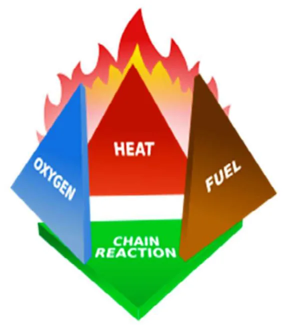
Classification of Fires and Fuel Sources
Quoted word for word — COMDTINST 16114.1B, ch. 5, D.2
The following are the four classes of fires: (01) Class A, (02) Class B, (03) Class C, (04) Class D.
Class A
Quoted word for word — COMDTINST 16114.1B, ch. 5, D.2.a
A Class A fire involves common combustible materials. Fuel sources within this class include wood and wood-based materials, cloth, paper, rubber, and certain plastics.
Class B
Quoted word for word — COMDTINST 16114.1B, ch. 5, D.2.b
A Class B fire involves flammable or combustible liquids, flammable gases, greases, and similar products. Fuel sources within this class include petroleum products.
Class C
Quoted word for word — COMDTINST 16114.1B, ch. 5, D.2.c
A Class C fire involves energized electrical equipment, conductors, or appliances.
Class D
Quoted word for word — COMDTINST 16114.1B, ch. 5, D.2.d
A Class D fire involves combustible metals. Fuel sources within this class include sodium, potassium, magnesium, and titanium.
Fire Hose
Description
Quoted word for word — COMDTINST 16114.1B, ch. 5, E.1
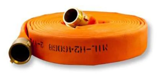
A fire hose is a basic fire fighting tool. Although taken for granted, hoses are highly developed tools that must be properly used and maintained. A standard fire hose is a double-jacketed, cotton or nylon-impregnated, rubber-lined, orange hose. It comes in 2 common diameters, 1½-inch or 2½- inch, and is produced in standard lengths of 50 feet. In some cases, a fire hose on smaller boats must be shorter than the standard length because of limited space. In many cases the fire hoses available on boats are a bit different than the standard double-jacketed, cotton or nylon-impregnated, rubber-lined, hose you see fire fighters using. It is a double jacketed, soft, nitrile rubber covered hose. The fire hose is used in conjunction with a dewatering pump and provides limited fire fighting capability.
CAUTION !
A charged hose has considerable force. Ensure it is properly manned at all times to prevent it from swinging out of control.
Safety Precautions
Quoted word for word — COMDTINST 16114.1B, ch. 5, E.2
Before using a fire hose, several safety checks must be performed. These checks may seem needlessly time-consuming at a fire scene. Nonetheless, they must be performed to prevent a malfunction in a hose system that could cause even more time to be lost. The following checks should be performed: (01) Make certain all hose connections are tight and a hose is free of kinks and twists. (02) Ensure the bail on a nozzle is closed before a hose is charged. (03) Never lay a hose on an excessively hot deck. (04) Be sure there are enough people available to control a fire hose before charging it. Never leave a charged hose unattended.
Minimum Operators
Quoted word for word — COMDTINST 16114.1B, ch. 5, E.3
A minimum of two people is recommended to control a 1½-inch hose.
Coupling
Quoted word for word — COMDTINST 16114.1B, ch. 5, E.4
A fire hose has brass or metal fittings, known as male and female couplings at its ends. This allows one hose to be attached to another or to a fitting. A female coupling connects to a boat’s fire main or portable pump. A male coupling connects to a nozzle or to a female coupling on another length of hose. To connect lengths of fire hose, crewmembers take half a turn to the left on the female coupling to set the threads and then turn to the right until the connection is tight. Fittings should be hand tight.
Spanner Wrench
Description
Quoted word for word — COMDTINST 16114.1B, ch. 5, E.5
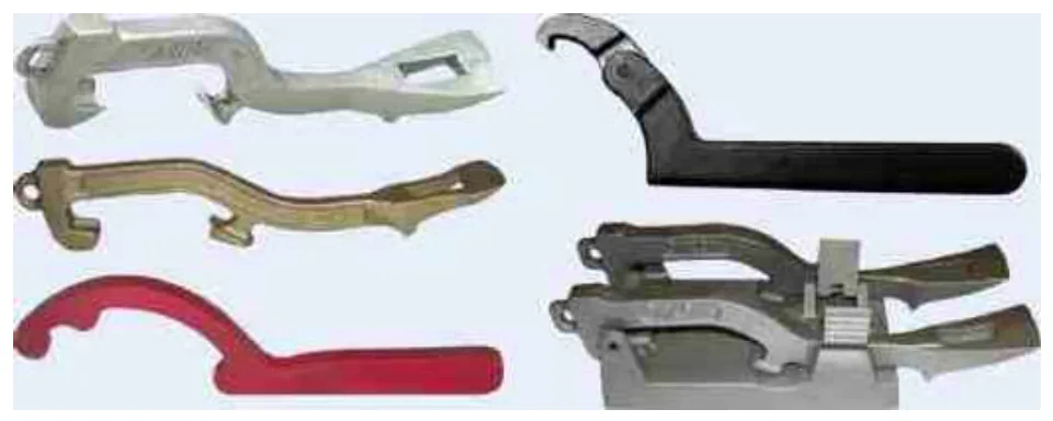
Spanner wrenches are very important when working with fire hoses. As mentioned before, when connecting fire hoses to fittings or another hose, connections should be hand tight, allowing for an easy disconnect. Sometimes tightening connections only hand tight is not enough. This is where a spanner wrench helps out. Spanner wrenches are also useful if a fire hose is unable to be disconnected from a connection because it has been put on too tight. A spanner wrench is adjustable so that is can be used with all standard sizes of fire hoses. A range of adjustment is indicated on the handle of a wrench. A curved tip on the working end of a wrench is made to fit all notches in a coupling.
Safety Precautions
Quoted word for word — COMDTINST 16114.1B, ch. 5, E.6
Spanner wrench safety precautions are as follows: (01) As with using any wrench, be careful not to get fingers or other objects caught between the wrench and the coupling. (02) Ensure the working end of the wrench is in the notch before applying heavy pressure.
Operation
Quoted word for word — COMDTINST 16114.1B, ch. 5, E.7
On properly maintained hoses, connections may be effectively tightened by hand. However, if there is water leakage at a connection, a spanner wrench (Figure 5-13) may be used. Once a wrench is adjusted, the tip of a wrench is inserted into the notch and the wrench handle pulled to the right.
Vari-Nozzle
Description
Quoted word for word — COMDTINST 16114.1B, ch. 5, E.8
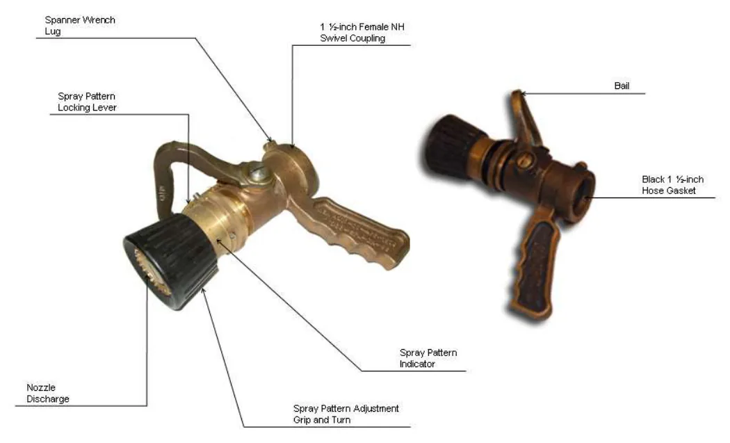
The vari-nozzle can be used for fighting all classes of fires. In the fog position, it can also be used for personnel protection by creating a shield of water spray. A Navy vari-nozzle is fitted with a pistol grip handle on the underside of the nozzle and a two-position bail handle on the top that operates the nozzle. The vari-nozzle’s spray pattern is adjusted by rotating the variable pattern tip and can range from a 90° wide-angle spray to a narrow straight stream as well as intermediate patterns between these extremes.
Operation
Quoted word for word — COMDTINST 16114.1B, ch. 5, E.9
This nozzle (Figure 5-14) is used with AFFF for extinguishing Class B fires.
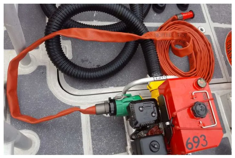
CG-P6 Portable Dewatering Pump with Attached Fire Fighting Hose and Nozzle
Description
Quoted word for word — COMDTINST 16114.1B, ch. 5, E.10
The CG-P6 portable dewatering pump with attached fire fighting hose and nozzle is used to suppress fire aboard vessels. Coast Guard personnel shall not engage in independent fire fighting operations, except to save a life or in the early stages of a fire to avert a significant threat without undue risk.
Minimum Operators
Quoted word for word — COMDTINST 16114.1B, ch. 5, E.11
The CG-P6 portable dewatering pump with fire fighting hose and nozzle is operated by a minimum of two boat crew members; one to operate/monitor CG-P6 and one to control and direct the hose and nozzle. Coast Guard personnel shall not engage in independent fire fighting operations except to save life, or
WARNING
in the early stages of a fire to prevent a significant threat without undue risk. See Reference (m) for additional policy guidance.
CG-P6 Dewatering Pump
Quoted word for word — COMDTINST 16114.1B, ch. 5, E.12
The CG-P6 portable dewatering pump consists of a 6 ½ horsepower, 4-cycle gasoline driven engine with a rated output of 250 gallons of water per minute at a 12-foot suction lift. Under load this pump will operate for approximately 4 to 5 hours on a full tank of gasoline. Refer to Chapter 5, Section B.13 for procedures on operating the CG-P6 Portable Dewatering Pump.
Fire Fighting Hose
Quoted word for word — COMDTINST 16114.1B, ch. 5, E.13
A 50-foot fire fighting hose (Figure 5-15) with a 1 ½-inch male coupling (attached to nozzle) and 1 ½-inch female coupling (attached to black outlet adapter) that is connected to the CG-P6.
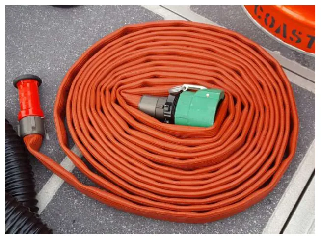
Fire Fighting Nozzle
Quoted word for word — COMDTINST 16114.1B, ch. 5, E.14
A 1 ½-inch fire fighting nozzle (Figure 5-16) is attached to one end of the 50- foot fire fighting hose. The nozzle has a rated output of 75 gallons per minute (GPM).
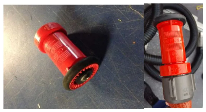
Quick Connection Coupling (Applicable Assets)
Quoted word for word — COMDTINST 16114.1B, ch. 5, E.15
A 6-foot by 3-inch suction hose (Figure 5-17) for connecting the CG-P6 to an installed standpipe is available on certain boat types (e.g., MLB, RB-M).
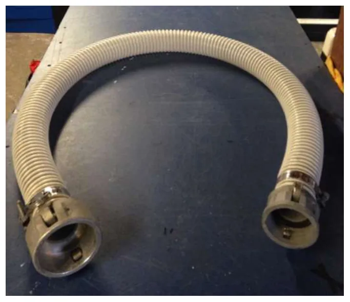
CG-P6 Discharge Outlet Adapter
Quoted word for word — COMDTINST 16114.1B, ch. 5, E.16
A 3-inch color-coded coupling (Figure 5-18) attached to the discharge outlet of the CG-P6 to allow the attachment of the 50-foot fire fighting hose.
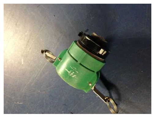
Fire Fighting Hose and Nozzle Operation
Quoted word for word — COMDTINST 16114.1B, ch. 5, E.17
All crewmembers should become familiar with these instructions and practice operating the CG-P6 with fire fighting hose and nozzle attached. The following procedures outline the basic steps for setting up and operating the CG-P6 pump with fire fighting hose and nozzle attachments (Figure 5-19).
NOTE
Refer to the manufacturer instructions for specific information on pump operation and maintenance. Breathing exhaust fumes can be dangerous. Do not attempt to start or operate a pump while it is in a
WARNING
container. Once a pump is started, ensure sufficient ventilation is present to allow exhaust gases to dissipate into the atmosphere. Do not operate a drop pump below deck.
| Step | Procedure |
| 1 | Pull the handle to release the tension ring or undo the locking clips on the storage container. |
| 2 | Lift the lid and open the plastic bag. Lift out the drop pump, hoses, and fuel. |
| 3 | Check the engine oil level (oil must be visible). |
| 4 | Check the fuel tank (fill if needed) and then connect fuel line to the fuel tank. |
| 5 | If applicable, open fuel vent cap by turning counter clockwise. |
| 6 | Fake out fire hose on deck so there are no kinks or twists. Connect fire hose. During operation, the fire fighting hose should be manned at all times. |
| 7 | Attach connection end of suction hose to “Yellow” attachment point of CG-P6 and lower strainer end into the water or connect fire fighting standpipe suction hose on applicable platforms. |
| 8 | Turn the engine IGNITION switch to the “ON” position. |
| 9 | Open the fuel valve on the engine by pushing it to right into the “ON” position. |
| 10 | Move the choke lever to the “CLOSED” position. |
| 11 | Set throttle to approximately 1/3 open. |
| 12 | Prime the pump by rapidly cycling the primer handle in and out until water is discharged from the primer cylinder cap. |
| NOTE If unable to obtain suction from standpipe pickup, then switch to standard suction hose included in pump container. | |
| 13 | Start the pump by pulling the recoil starter rope. |
| 14 | Move the choke lever to the “OPEN” position once the engine starts. |
| 15 | Rapidly cycle the hand primer handle until the fire hose is charged. |
| 16 | Move throttle through its full range accordingly, checking for maximum flow output. |
| 17 | Post a watch on the pump. The engine will run approximately 4-5 hours on one tank of fuel. The pump watch must be alert for debris around the strainer and must ensure the strainer remains submerged. |
Securing in an Emergency
Quoted word for word — COMDTINST 16114.1B, ch. 5, E.18
Perform the following procedures for securing:
| Step | Procedure |
| 1 | Turn the engine IGNITION switch counterclockwise to the “OFF” position. If engine fails to secure, “disconnect quick fuel fitting” from the fuel tank. |
NOTE
Securing for storage refer to Chapter 5, Section B.13.c.2. Securing for Storage.
How Extinguishing Agents Work
Description
Quoted word for word — COMDTINST 16114.1B, ch. 5, F.1
Extinguishing agents put out fires by breaking one or more of the four elements of a fire tetrahedron. They work by cooling, smothering, chain breaking, or by a process called oxygen dilution. (01) Cooling reduces the temperature of a fuel source below the fuel’s ignition point. (02) Smothering separates a fuel source from its oxygen supply. (03) Chain breaking disrupts the chemical process necessary to sustain a fire. The element of a chain that is broken depends upon the class of fire and the type of extinguishing agent used. (04) Oxygen dilution is a smothering process that reduces the amount of oxygen available to a level below that required to sustain combustion. The different fire classes, the fuel source for each class, the type of extinguishing agent for each class, and the primary effect of each agent are described as follows:
| Class | Fuel Sources | Primary Extinguishing Agent | Primary Effect |
| A | Common combustible materials such as wood and wood-based materials, cloth, paper, rubber, and certain plastics. | (01) Water (02) PKP (dry chemical) | Removes the heat element. |
| B | Flammable or combustible liquids, flammable gases, greases, petroleum products, and similar products. | (03) Foam Aqueous Film Forming Foam (AFFF) (04) CO2 (05) PKP (dry chemical) | Removes the oxygen element. |
| C | Energized electrical equipment, conductors, or appliances. | (06) CO2 (Carbon Dioxide) (07) PKP (dry chemical) | Removes the oxygen element, and temporarily removes elements of oxygen and heat. |
| D | Combustible metals, such as sodium, potassium, magnesium, and titanium. | (08) Water (high velocity fog) (09) Sand (placed underneath the metal) | Removes the heat and oxygen elements. |
Applying Water
Description
Quoted word for word — COMDTINST 16114.1B, ch. 5, F.2
Onboard some boats, water for fire fighting comes from a portable dewatering/fire pump. Some boats have a built-in fire pump through the fire main and hose system or from portable fire pumps. Water is applied to a fire using one of three ways: (01) Straight stream, (02) Narrow fog (30°), (03) Wide fog (90-110°).
Straight Stream
Quoted word for word — COMDTINST 16114.1B, ch. 5, F.3
A straight stream of water is used when long reach and penetrating power are critical.
Class A Fires
Quoted word for word — COMDTINST 16114.1B, ch. 5, F.3.a
On Class A fires, its primary purpose is to break up burning material and to penetrate the base of a flame. Therefore, a straight stream must be directed at the base of flames in a Class A fire.
Class B Fires
Quoted word for word — COMDTINST 16114.1B, ch. 5, F.3.b
A straight stream of water is not effective for extinguishing Class B fires. It can cause a violent fire reaction if a water stream atomizes fuel into the air causing an increased surface area. It could also splash the burning liquids spreading the fire to different areas.
Class C Fires
Quoted word for word — COMDTINST 16114.1B, ch. 5, F.3.c
A straight stream of water should not be used on a Class C fire because it is a conductor of electricity. Electric current could travel back through a stream of water and be hazardous to a fire fighting team.
Class D Fires
Quoted word for word — COMDTINST 16114.1B, ch. 5, F.3.d
A straight stream can also be used on Class D fires for cooling and to wash burning materials over the side.
Narrow Fog
Quoted word for word — COMDTINST 16114.1B, ch. 5, F.4
Use of narrow fog is also an effective method of extinguishing fires.
Class A Fires
Quoted word for word — COMDTINST 16114.1B, ch. 5, F.4.a
Narrow fog is more useful than a straight stream on Class A fires. One reason is that narrow fog can cool a much wider surface than a stream and, consequently, it can absorb more heat. Additionally, as fog comes into contact with any surface heated by fire, it becomes steam. Steam provides a secondary smothering effect that further aids in extinguishing the fire.
Class B Fires
Quoted word for word — COMDTINST 16114.1B, ch. 5, F.4.b
Because of the cooling qualities of finely divided water particles, narrow fog is a successful extinguishing agent on Class B fires. Narrow fog should be used on flammable liquids only when AFFF is not available.
Class C Fires
Quoted word for word — COMDTINST 16114.1B, ch. 5, F.4.c
When water is broken into small particles (nozzle fog patterns), there is little danger of its carrying electric current making narrow or wide fog safe to use on Class C fires. However, the nozzles should be operated at least four feet from a fire source.
Class D Fires
Quoted word for word — COMDTINST 16114.1B, ch. 5, F.4.d
Water is the recommended agent for Class D fires when applied in quantity as fog patterns. When water is applied to burning Class D materials, there may be small explosions. The firefighter should apply water from a safe distance or from behind suitable shelter. Class D materials will continue burning until the material is completely consumed, but cooling streams of water can control the burn. However, efforts should be directed at jettisoning or washing the materials over the side to avoid accumulating fire-fighting water inside the vessel. Water fog can also be used to protect fire fighters from excessive heat.
NOTE
Nozzles can pose an electrical shock hazard to fire fighters. If a nozzle or solid stream accidentally contacts electrical equipment or circuits, an electrical charge may be conducted back to the nozzle operator and cause injury.
Wide Fog
Quoted word for word — COMDTINST 16114.1B, ch. 5, F.5
Wide fog is applied with a vari-nozzle. Wide fog is a pressurized spray less powerful than narrow fog. Because wide fog covers more area than narrow fog, it may be used most effectively when it is possible to get right up next to the fire. Wide water fog can also provide a heat shield by forming a screen of water droplets between a firefighter and the fire. When fire fighters are properly clothed and hose lines have vari-nozzles, it is not necessary to use low-velocity water for personal protection. Fog streams used improperly can injure personnel. The fog screen from narrow fog can obscure a nozzleman’s visibility. This is extremely important to remember when no opening exists in the compartment or passageway other than the opening through which the nozzle is being advanced. In spaces with only one opening, heat and smoke can blow back or burst through or around a fog curtain. When circumstances require entering a compartment or passageway that has only one opening, short bursts of solid stream or fog should be directed toward the overhead to knock down the flames. Using water as an extinguishing agent adds water and weight to a vessel. This can cause the vessel to become unstable. Normally, the water will be removed (dewatered) after the fire has been extinguished. However, to maintain stability and decrease the threat to the crew, the vessel should be dewatered as soon as possible.
Effectiveness
Quoted word for word — COMDTINST 16114.1B, ch. 5, F.6
Water can be effective on all classes of fire, when properly applied for the situation. However, it is most effective for Class A fires. It is recommended for use in Class D (combustible metals) fires for its cooling effect and ability to wash the material away.
Adapting Equipment
Quoted word for word — COMDTINST 16114.1B, ch. 5, F.7
While the high velocity and low velocity fogs described above are effective, it is important to remember that the limited fire fighting capability on most boats requires some adaptation to ensure a fog is applied. Since a fog stream is essentially a stream of water that has been broken up into smaller droplets, you can use the equipment available to achieve this. It could be as simple as splitting the water flow by hitting a rung on a ladder or by deflecting the stream off a bulkhead or deck.
Applying Aqueous Film-Forming Foam (AFFF)
Description
Quoted word for word — COMDTINST 16114.1B, ch. 5, F.8
Foam is a blanket of bubbles that extinguishes a fire mainly by smothering. The bubbles are formed by mixing water, air, and a foam-producing agent called foam concentrate. The mixture of water, air, and foam concentrate becomes foam solution. When using foam, the entire surface of a flame must be covered, otherwise uncovered areas will continue to burn. One gallon of liquid foam concentrate will produce approximately 133 gallons of foam solution. The contents of one 5-gallon can of liquid foam will last about 1½ minutes and will produce about 660 gallons of foam solution. Foam may be used against Class C fires in an emergency and as a last resort. AFFF concentrate separates at temperatures below 35 °F. This does not affect its usefulness provided the can is shook to re-mix components before use.
Effectiveness
Quoted word for word — COMDTINST 16114.1B, ch. 5, F.9
Foam is effective against Class B fires. Foam solution is lighter than the lightest of flammable liquids. When applied to burning liquids, it floats on the surface and prevents oxygen from reaching the fuel source. In addition, the water content of foam provides a cooling effect on the fire. Once the fire is out, a layer of foam should be maintained over the flammable liquid to ensure the fire stays extinguished.
Applying Chemical Agents
Description
Quoted word for word — COMDTINST 16114.1B, ch. 5, F.10
Chemical agents can be very effective fire fighting tools. However, they can be ineffective and sometimes dangerous if they are not used properly. Learning the proper use of each chemical agent, including its advantages and disadvantages, before using it to fight a fire is essential. Two chemical agents are discussed below: (01) Carbon dioxide (CO2). (02) Dry Chemical /Potassium bicarbonate (PKP).
Carbon Dioxide (CO2)
Quoted word for word — COMDTINST 16114.1B, ch. 5, F.11
CO2 is a colorless gas about 50 percent heavier than air. When released from its container, the gas expands to 450 times its stored volume and smothers a fire by temporarily removing the oxygen. Because it is a non-conductor of electricity, CO2 is the primary agent for class C fires.
CAUTION !
CO2 should never be used alone to fight a major fire.
CO2 Effectiveness
Quoted word for word — COMDTINST 16114.1B, ch. 5, F.11.a
CO2 is effective on small class A, B, and C fires. It has a very limited cooling capacity and does not permanently remove oxygen from a fuel source. Therefore, CO2 is only effective in knocking down flames. Unless CO2 is used continuously until all flames are extinguished, the fire could re-ignite (re-flash). In fact, the likelihood of a re-flash is greater when CO2 is used against a fire than any other type of agent. A continuous discharge of CO2 from a fully charged 10-pound extinguisher will last approximately 40 to 45 seconds. The effective range for the portable CO2 extinguisher is approximately 5 feet. A distance of more than 5 feet may cause the CO2 to mix with the air and become ineffective.
Discharging CO2
Quoted word for word — COMDTINST 16114.1B, ch. 5, F.11.b
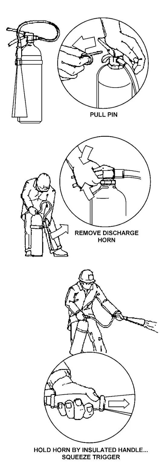
CO2 gas is not a conductor of electricity. However, when discharging the CO2, static electricity may build up in the horn. This could be quite dangerous when extinguishing a fire where explosive gases are present. The cylinder should always be kept grounded to the deck when discharging to prevent static charge buildup. CO2 is most effective in closed spaces away from the effects of strong winds. The following are the operating procedures (Figure 5-20) for the CO2 extinguisher:
| Step | Procedure | |
| 1 | Remove the locking pin from the valve. | |
| 2 | Carry the extinguisher in an upright position, approaching the fire as close as safety permits. | |
| 3 | For the smaller 5-pound size, swing the horn up to a horizontal position. | |
| 4 | For larger CO2 extinguishers, ensure the CO2 bottle is in contact with the deck to prevent a static charge from building up within the extinguisher. | |
| 5 | Grasp the insulated horn handle and squeeze the release lever to start the extinguisher. | |
| 6 | Direct the flow of CO2 toward the base of the flame and attack the flame with a sweeping movement of the nozzle. |
WARNING
CO2 is extremely cold when discharged. The rapid expansion of the gas creates a “snow” that can “burn” or raise blisters if it comes in contact with bare skin. Keep hands on the insulated horn handle when using the CO2 extinguisher.
Dry Chemical / Potassium Bicarbonate (PKP)
Quoted word for word — COMDTINST 16114.1B, ch. 5, F.12
PKP is also known as purple K powder. The ingredients used in PKP are non- toxic. When PKP is applied, a dense cloud is formed in the combustion area that limits the amount of heat that can be radiated back to the heart of the fire. Fewer fuel vapors are produced due to the reduced radiant heat. The dry chemical PKP extinguishes flames by breaking the combustion chain.
CAUTION !
Dry Chemical/ PKP, like CO2, should never be used alone against a major fire for it presents the same hazard of a re-flash as CO2.
Dry Chemical/PKP Effectiveness
Quoted word for word — COMDTINST 16114.1B, ch. 5, F.12.a
Dry chemical extinguishers do not have cooling capability. PKP may be effective as a temporary measure for extinguishing a flame, but it dissipates rapidly. Therefore, all hot spots must be cooled to prevent re-ignition. It is effective to some degree on all types of fires, but is particularly effective when used against burning liquids. By first extinguishing a burning liquid with PKP and then laying down a blanket of AFFF to prevent re-flash, dealing with a Class B fire is very effective. Most dry chemical/PKP extinguishers have an effective range of 10-12 feet and will last between 8-20 seconds in continuous use.
Discharging Dry Chemicals
Quoted word for word — COMDTINST 16114.1B, ch. 5, F.12.b
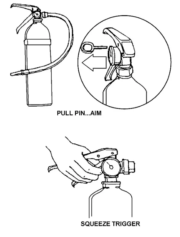
The dry chemical or powder contained in these portable containers is expelled by either a gas cartridge or by stored pressure within the container. The following are the procedures (Figure 5-21) for using this type of extinguisher:
| Step | Procedure |
| 1 | Operate the dry chemical extinguisher by following the instructions printed on the extinguisher. |
| 2 | Control the discharge of the dry chemical by the nozzle shutoff valve for both cartridge-operated and pressurized dry chemical extinguishers. |
| 3 | Approach the fire as close as safety will allow. |
| 4 | Remove pin. |
| 5 | Squeeze trigger. |
| 6 | Direct the discharge at the base of the flame and attack with a sweeping movement. |
Fire Suppressions Systems
Description
Quoted word for word — COMDTINST 16114.1B, ch. 5, F.13
A fire suppression system is used for extinguishing fires in the engine room where Class B and C fires occur.
Types
Quoted word for word — COMDTINST 16114.1B, ch. 5, F.14
There are several types of fixed fire extinguishing systems used aboard various boat platforms, to include: CO2, Halon, FM-200, HFC-227, and FE- 241. These systems are to be used only in emergency situations to control a fire in the engine room space. Refer to specific boat platform Operator’s Handbook for detailed procedures on system use.
WARNING
Ensure all personnel have evacuated the Engine Room before activating the fire suppression system. Activating the system with personnel in the space can result in injury or death.
Coast Guard¶s Fire Fighting Duty
Quoted word for word — COMDTINST 16114.1B, ch. 5, G.1
Fire Fighting is not a primary mission of the Coast Guard. Because of the limited capability, all fire fighting activities should be limited to only those in accordance with Section 4.4.2.2 of Reference (j). Section 4.4.2.2 states that Coast Guard personnel shall not engage in independent fire fighting operations except to save life, or in the early stages of a fire to prevent a significant threat without undue risk. It also states that for fire fighting activities involving commercial vessels and waterfront facilities, Coast Guard personnel shall not actively engage in fire fighting except in support of a regular fire fighting agency under the supervision of a qualified fire officer.
NOTE
A qualified fire officer is a person who has been trained and certified, under National Fire Protection Association guidelines, to take command of fire fighting operations. A boat crew is faced with several responsibilities and decisions when a vessel or waterfront fire occurs. Decisions made may affect lives, millions of dollars in property, and the free flow of maritime commerce. When determining a unit¶s assistance posture, the following should be considered: (01) Level of the threat of fire. (02) Jurisdictions involved. (03) Capabilities of local fire departments. (04) Availability and capability of Coast Guard equipment. (05) Level of training.
Personnel Training
Quoted word for word — COMDTINST 16114.1B, ch. 5, G.1.a
Coast Guard personnel engaged in fire fighting operations must be properly trained and equipped for the task they are assigned. Therefore, the level of Coast Guard involvement is dependent upon available leadership, experience, training, and equipment. Coast Guard planning and training efforts must be integrated with those of other responsible agencies, particularly local fire departments and port authorities. This is especially important for fires on large vessels and shore structures. COTPs work closely with municipal fire departments, vessel and facility owners and operators, mutual aid groups, and other interested organizations. COTPs have developed a fire fighting contingency plan that addresses fire fighting in each port in the COTP zone.
Safety Precautions
Quoted word for word — COMDTINST 16114.1B, ch. 5, G.2
Fire fighting can be very hazardous to anyone involved. Personnel must always be alert and aware of their actions and decisions to avoid being injured or incapacitated. Losing the services of any crewmember may keep a boat crew from preventing other injuries, loss of life, or loss of property. Refer to Reference (h) for a discussion of risk assessment and risk management.
Salvors and Marine Chemists
Quoted word for word — COMDTINST 16114.1B, ch. 5, G.2.a
Shipboard and waterfront fires frequently involve toxic or chemical hazards for fire fighters. These hazards may be the source of the fire or produced as a by-product of fire. Therefore, caution must always be exercised before attempting to fight any type of fire. Requesting trained assistance before becoming involved in fighting a fire of unknown material would be prudent. Many salvage companies operate over a wide geographic area. Thus, these companies can respond more quickly to these situations. In addition, they employ marine chemists who can obtain temperature readings, check for the presence and concentrations of gases, and can provide information to fire fighting forces about chemical hazards they may encounter during response activities.
Smoke Plumes
Quoted word for word — COMDTINST 16114.1B, ch. 5, G.2.b
Coxswains must always keep their boats well clear of smoke plumes rising from a fire because they greatly reduce visibility and can pose a health hazard. Smoke is a visible product of fire and carries water vapor, acids, and other chemicals produced by fire and can be irritating or toxic when inhaled. A smoke plume is made of suspended particles of carbon and other unburned substances. These products of combustion are released into the atmosphere and travel downwind.
Staying Upwind
Quoted word for word — COMDTINST 16114.1B, ch. 5, G.2.b.1
As a plume expands downwind and outward from a fire, toxic products will be less concentrated. The more toxic a product is, the larger the unsafe area will be, both downwind and to the sides of a plume. The decision to set a perimeter upwind of a toxic smoke or fire plume must be considered and executed when prudent. Individuals who remain a safe distance upwind should not be affected by unseen dangers of a smoke plume.
NOTE
Generally speaking, remaining upwind of the fire provides a safe area away from toxic hazards that are released in a fire plume.
Maintaining a Safe Distance
Quoted word for word — COMDTINST 16114.1B, ch. 5, G.2.b.2
Other decisions, such as determining a safe distance from a plume of smoke, should be made and constantly re-evaluated as an incident develops. Any change in weather conditions could dictate a need to increase the initial size of a perimeter. A crewmember is considered to be in a danger zone if a smoke plume is visible and radiant heat is felt.
Awareness of Gases and Vapors
Quoted word for word — COMDTINST 16114.1B, ch. 5, G.2.b.3
Smoke plumes also have other factors that must be considered such as the behaviour of gases or vapors that extend beyond a perimeter of visible smoke and fire. Burning plastics and rubber products produce gases, heat, flame, and smoke. These by-products may contain elements of a toxic or lethal nature. There are many other products of combustion that are dangerous and can be lethal under certain conditions.
Action
Quoted word for word — COMDTINST 16114.1B, ch. 5, G.3
When a boat crew becomes involved in fire fighting operations, the situation will typically be one that fosters a great sense of urgency to extinguish a fire as rapidly as possible. All members of a boat crew must remember that haste and lack of a coordinated effort by boat crewmembers can recklessly endanger a boat and all crewmembers.
Crew Brief
Quoted word for word — COMDTINST 16114.1B, ch. 5, G.3.a
A coxswain must brief crewmembers before arriving at the scene of a fire. This briefing details each crewmember’s assignments and emphasizes safety. Crewmembers are responsible for all duties assigned and must request clarification from the coxswain if they do not clearly understand the tasks assigned. They must break out all necessary gear. All personnel must don battle dress before arriving on scene. Battle dress means that everyone will button their collars, roll their sleeves down, wear gloves (if available), and ensure pants are bloused or tucked into their socks. The coxswain is responsible for inspecting all other crewmembers and making certain that battle dress has been donned.
Initial Action
Quoted word for word — COMDTINST 16114.1B, ch. 5, G.3.b
The following are procedures initially performed when responding to a fire:
| Step | Procedure |
| 1 | If possible, approach the boat from upwind. |
| 2 | Immediately upon arriving on scene, all crewmembers should check the surrounding vicinity for PIWs. |
| 3 | Recover and evacuate all survivors to the vessel. |
| 4 | Evaluate their physical conditions and render first aid if necessary. |
| 5 | If the extent of injury requires more than minor first aid, immediately transport the injured so they can receive professional medical assistance. |
| 6 | Inform operational command and EMS if necessary, of the situation. |
These procedures are to be taken before attacking the fire, remembering that life comes before property. If there are no survivors or those recovered are in good physical condition and have been evacuated to a safe place, the next step is evaluating the fire.
WARNING
If the risk of explosion is not certain, back off a safe distance and establish a safety zone. Do not attempt to fight the fire.
CAUTION !
A crewmember’s decision regarding his or her role in the overall situation must be constantly reexamined.
Situation Evaluation
Quoted word for word — COMDTINST 16114.1B, ch. 5, G.3.c
The coxswain and crew must evaluate the following elements of the situation: (01) Location and extent of a fire. (02) Class of fire. (03) Class and extent of all cargo involved. (04) Possibility of explosion. (05) Possibility of any vessel involved sinking/capsizing within a navigable channel. (06) Hazard to the crew. (07) Maneuverability of the vessel. (08) Weather forecast. (09) Risk of a serious pollution incident.
| Step | Procedure |
| 1 | If a fire can be put out with no danger to the crew or the vessel, proceed. |
| 2 | If not, back off and maintain a safety zone so that no other vessel comes too close to the fire scene. |
| 3 | After completing the initial evaluation, re-evaluate a fire scene/situation frequently. A small fire can rage out of control in minutes and threaten more property and cargo. |
| 4 | If a fire must be approached at any time, remember to always approach from windward (Figure 5-22). |
| 5 | If it becomes necessary to tie up alongside a burning vessel to fight a fire or to remove survivors, attach only one line to the vessel and keep a sharp knife accessible for a quick break away. |
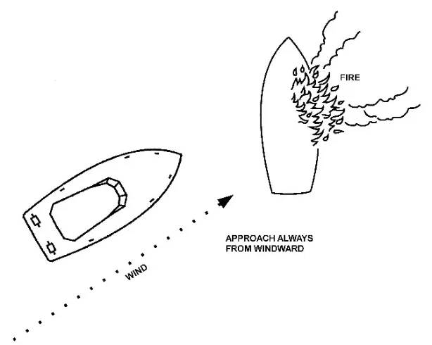
Overhauling
Quoted word for word — COMDTINST 16114.1B, ch. 5, G.3.d
Danger will still exist even after a fire is believed to be extinguished. The process of overhauling the fire is done to avoid fire re-flash as follows:
| Step | Procedure |
| 1 | When a fire is out, check for hot spots and set a re-flash watch. |
| 2 | When danger of re-flash is no longer a concern, dewater the distressed vessel. |
Safety Rules
Quoted word for word — COMDTINST 16114.1B, ch. 5, H.1
The following safety rules should be observed when using portable fire extinguishers: (01) Immediately upon discovering a fire, sound an alarm and summon help. Never try to fight a fire alone. Always call for help first. (02) Never pass a fire to get to an extinguisher. (03) If it is necessary to enter a compartment to combat a fire, keep an escape path open. Never let a fire block a door, hatch, or scuttle. Stay low. (04) If extinguishing a fire within a compartment with a portable fire extinguisher fails, get out. Then close the door, hatch, or scuttle to confine the fire.
Fire Combat
Quoted word for word — COMDTINST 16114.1B, ch. 5, H.2
An attack should be started immediately to gain control and to prevent extension of a fire to other areas of a boat. An attack will be either direct or indirect, depending on the fire situation. Both methods are efficient when properly employed.
Direct Attack
Quoted word for word — COMDTINST 16114.1B, ch. 5, H.3
A direct attack may be used if a fire is small and has not gained headway. For a direct attack, crewmembers advance to the immediate area of a fire and apply extinguishing agent directly on the fire. Once a fire has gained headway, an indirect attack should be used.
Indirect Attack
Quoted word for word — COMDTINST 16114.1B, ch. 5, H.4
An indirect attack is best when it is impossible for crewmembers to reach a fire. Generally, this is in the lower portions of a boat, such as the engine room and bilge areas. The success of an indirect attack depends on completely containing a fire. Every possible avenue a fire may travel must be cut off by closing doors, hatches, and scuttles and by securing all ventilation systems.
Fire Fighting Procedures Onboard Own Boat
Quoted word for word — COMDTINST 16114.1B, ch. 5, H.5
Every fire will quickly spread to new sources of fuel or oxygen if they are available. However, the path through which a particular fire extends will depend on the location of a fire and the construction of surrounding spaces. These factors must be considered when fighting a fire. In addition, fuel and other combustible products will affect fire fighting operations. For these reasons, no fire can be fought routinely, and all fires must be fought systematically. The following procedures should be part of every fire fighting operation:
CAUTION !
Never fight a fire, however small it may seem, until an alarm has been sounded. Once a fire gains intensity, it spreads swiftly.
| Step | Procedure |
| 1 | Sound an alarm. Any crewmember who discovers a fire or any indication of fire must sound an alarm and give a location (e.g., “FIRE, FIRE, FIRE IN THE BILGES”). |
| 2 | Evaluate a fire. (01) Determine the air supply to the fire. (02) Determine the class of fire (combustible material). (03) Determine the fuel source to the fire. (04) Select proper extinguishing agent. (05) Determine method for fighting a fire (direct or indirect). (06) Determine how to prevent spread of a fire. (07) Determine required equipment and crewmember assignments. |
| Step | Procedure |
| 3 | Determine the need to secure: (01) Electrical and electronic power panels. (02) Power to individual electrical and electronic equipment (alternator, radar, inverters). (03) Engine and fuel supply. (04) Air intakes (ventilation system, doors, hatches and scuttles). |
| 4 | Place all equipment necessary to combat a fire in an open deck area. This includes: (01) Portable fire extinguishers. (02) Fire hoses. (03) AFFF. (04) Drop pump. (05) First aid kit. |
| CAUTION ! Water can impair the stability of a boat. Make every effort to limit accumulation of water in compartments. Give preference to fog sprays over solid streams of water. Use only as much water as is absolutely necessary. | |
| 5 | Combat a fire with appropriate extinguishing agent(s). |
| 6 | Notify parent unit at the earliest opportunity. Keep them fully advised of the situation. (01) Give position. (02) Nature of fire. (03) Number of POBs. (04) Your intentions. (05) Keep them advised of changing situation and status of personnel. |
| Step | Procedure |
| 7 | Overhaul the fire. (01) Once the fire has been extinguished, the spaces involved must be properly ventilated to remove any smoke, explosive, or toxic gases. If there is any doubt as to whether the space might contain harmful fumes, do not enter that compartment. Return to the Station and have the space checked out by trained officials. Be careful when ventilating because the introduction of fresh air into a compartment might cause the fire to re-flash. (02) Once in the space, inspect all overhead spaces, decks, and bulkheads. (03) Check where wiring and piping penetrates through bulkheads and decks. (04) Expose areas that are charred, blistered, or discolored by heat until a clean area is found. (05) Pull apart and examine any materials that might have been involved with the fire for hidden fire and hot embers. Jettison (throw overboard) all such material if necessary. (06) Set a re-flash watch. One crewmember must be assigned to do nothing but check for re-ignition and to sound an alarm if it occurs. |
| 8 | Re-stow all fire fighting equipment except those pieces that are being used by the re-flash watch. (01) Recharge or replace portable fire extinguishers, even if only partially used, immediately upon arrival back at the unit. (02) Swap out used fire hoses with spare dry hoses. Drain, clean, dry, and roll up used hoses for storage. |
| 9 | Conduct a damage control check. Start any necessary dewatering operations. Depending on the severity of the damage, it might be best to tow the damaged vessel back to port where an in depth determination concerning damage to the vessel’s systems can be conducted. Utilizing possibly damaged electrical or mechanical equipment might cause further damage or another fire. |
Fire Fighting Procedures on Auxiliary Boats
Quoted word for word — COMDTINST 16114.1B, ch. 5, H.6
Use the following procedures when battling a fire on an Auxiliary boat:
| Step | Procedure |
| 1 | When a crewmember becomes aware of an engine compartment fire, shut off all engines, generators, and ventilation systems. |
| 2 | If boat is equipped with an automatic extinguishing system, ensure it is discharging. If the system is manually operated, energize it and check to ensure it is discharging. |
| 3 | Initiate a MAYDAY call to alert boats in the area of the situation. |
| 4 | Have all crewmembers don PFDs and everyone move to a smoke-free and flame-free area of the boat. |
| 5 | If a life raft or dinghy is available, put it over the side and inflate it, if necessary. |
| 6 | (01) If boat has a built-in CO2 system, after fire is out, allow time for concentrations of CO2 to ventilate to the atmosphere before entering the compartment. (02) On boats fitted with a Halon system, the dangers of toxic gases are not as great when entering the compartment, but always enter with caution. Never enter a compartment after a fire until you are sure it has been properly ventilated. |
Opening a Hatch
Quoted word for word — COMDTINST 16114.1B, ch. 5, I.6.a
The possibility of burned hands and/or a singed face can be expected if someone must open a hatch to discharge a portable extinguisher. As the fresh air enters the compartment, it will feed the fire, and cause it to “blow up.” The best method of opening a hatch is to stand to the hinged side of the hatch. Then while wearing gloves or using something other than bare hands, the hatch can be pulled open. If the boat has a closed engine compartment, no fixed system, and is equipped with an access hole/plug (Figure 5-23), a portable extinguisher may be discharged through this hole.
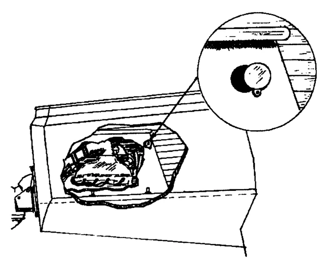
Fires Aboard Other Boats
Quoted word for word — COMDTINST 16114.1B, ch. 5, H.7
Use the following procedures when battling a fire aboard other boats to effect rescue of personnel:
| Step | Procedure |
| 1 | Brief crewmembers on appropriate procedures. |
| 2 | Assign each crewmember specific duties. |
| 3 | While en route to the scene, establish communications with the distressed boat. |
| 4 | Approach the boat from upwind. |
| 5 | If no one is onboard, circle the boat (at a safe distance) searching for PIWs. |
| 6 | Advise all persons aboard the boat to move to a flame and smoke-free area, topside. |
| 7 | Attempt to determine the extent and source of the fire. If it is not obvious, ask the personnel aboard the distressed boat where the fire is located. |
| 8 | If the fire is beyond the crewmembers fire fighting capabilities, evacuate the persons from the distressed boat and call for assistance. |
| 9 | Check the physical condition of the survivors. If medical treatment is required, proceed to the nearest location where medical help can be administered. |
| 10 | If the fire is small and within the crewmember’s capabilities, first ensure that the survivors are safe on the boat, another boat, or ashore before attempting to fight the fire. |
| 11 | After assessing the situation, fight the fire with the fire fighting equipment available. Avoid placing the crew and transferred survivors in any danger. |
Fire Under Control
Quoted word for word — COMDTINST 16114.1B, ch. 5, H.8
Under the following circumstances, a fire may be considered to be under control: (01) Extinguishing agent is being applied to a fire and has effectively begun to cool it down. (02) The main body of a fire (base) has been darkened. At this point, a fire cannot generate enough heat to involve nearby combustible materials. (03) All possible routes of fire extension have been examined and found safe or protected.
Fire Extinguished
Quoted word for word — COMDTINST 16114.1B, ch. 5, H.9
Before a fire can be declared completely out, ensure the following actions have taken place: (01) A thorough examination of the immediate fire area has been conducted. (02) A complete overhaul of all burned material has been accomplished. (03) A re-flash watch has been set. (04) All fire fighting equipment has been restowed with the exception of what is being used for the re-flash watch. (05) A damage control check has been performed. (06) All crewmembers have been accounted for. When possible, these activities should be conducted by local fire fighting professionals
Abandoning a Coast Guard Boat
Quoted word for word — COMDTINST 16114.1B, ch. 5, H.10
Crewmembers should not panic and hastily abandon a boat even when a fire is severe. Instead, they should stay calm while using equipment and training to combat the fire. Abandoning the boat should only be considered as a last resort once all available options for extinguishing the fire have been attempted. Aggressive and proficient fire fighting is normally a preferred alternative to abandoning a boat, however, crewmembers should not hesitate to abandon the boat if the following conditions exist: (01) Becoming trapped by the flames. (02) There is no longer the equipment to fight the fire. (03) An explosion is likely (flames by the fuel tanks). (04) Similar life threatening situations are apparent. If able, the coxswain should inform OPCON of location and any other pertinent information. Make sure that: (01) Distress call has been initiated. (02) All personnel are wearing life jackets. (03) Life raft or dinghy is put over, if available. (04) Portable radio is taken. (05) Extra signaling gear is taken.
PORTABLE FIRE-FIGHTING AND DEWATERING EQUIPMENT
Introduction
Quoted word for word — NAVEDTRA 14057-PPR, ch. 5, Introduction
Learning Objectives: To recall the characteristics and operation of various types of portable fire extinguishers, oxygen breathing apparatus for fire fighters, shipboard dewatering equipment and portable fans and blowers.
Aboard ship, Sailors use portable fire extinguishers to extinguish fires in compartments or in the galley. A fire-fighter’s ensemble provides protection for fire fighters, and the ensemble is enhanced by various types of oxygen breathing apparatus (OBA) for use when fire fighting or conducting gas-free testing or inspection. Additionally, dewatering equipment, which includes pumps and eductors, may have to be used when fighting fires along with other portable equipment, such as fans and blowers. The characteristics and operation of these types of equipment are presented in this chapter.
PORTABLE FIRE EXTINGUISHERS
Portable Fire Extinguishers
Quoted word for word — NAVEDTRA 14057-PPR, ch. 5, Portable Fire Extinguishers
Learning Objective: To recall the basic characteristics and operation of various types of portable fire extinguishers.
Portable fire extinguishers are used aboard all Navy ships, and the three types most often used are as follows:
• Dry chemical
• Carbon dioxide (CO2)
• Aqueous film-forming foam (AFFF)
DRY CHEMICAL EXTINGUISHER
Dry Chemical Extinguisher
Quoted word for word — NAVEDTRA 14057-PPR, ch. 5, Dry Chemical Extinguisher
Portable dry chemical extinguishers (fig. 5-1) are used primarily on class BRAVO fires. Purple-K-Powder (PKP) is the chemical most often used in these extinguishers. The dry chemical dispensed from the extinguisher interrupts the chemical reaction producing a fire and this action stops combustion.
Dry chemical is also safe and effective for use on class CHARLIE fires; however, carbon dioxide is preferred because PKP fouls electrical and electronic components. Also, PKP should not be used on internal fires of gas turbines or jet engines unless absolutely necessary because it also fouls engines. PKP is not effective on class ALPHA fires and can only be used to knock down flames and keep the fire under control until an appropriate extinguisher can be used.
PKP extinguishers come in an 18-pound and a 27-pound size. Most PKP extinguishers have a small CO2 cartridge mounted on the outside of the extinguisher shell. This cartridge provides the propellant charge for the extinguisher. Do NOT pressurize the PKP extinguisher until you are ready to use it.
The steps of the procedure you should adhere to when operating a dry chemical extinguisher are as follows:
Step 1. Carry the extinguisher to the scene of the fire.
Step 2. Remove the seal and pull the locking pin from the puncture lever marked PUSH.
Step 3. Push the puncture lever down to penetrate the seal of the CO2 cartridge. The extinguisher is now ready to use.
Step 4. Approach the fire from the windward side, if possible. Hold the extinguisher in one hand and the nozzle in the other hand.
Step 5. Discharge the dry chemical by squeezing the squeeze grip on the nozzle. Hold the nozzle firmly and direct the dry chemical at the base of the fire. Use a wide-sweeping motion from side to side. This will apply a dense, wide cloud of dry chemical over the area. Remember that the 27-pound extinguisher has a 21-foot range and the 18-pound extinguisher has a reach of 19 feet.
Step 6. Be certain that all of the fire in the area in which you are working is extinguished before you move in farther. If the fire appears to be too large or if there is a possibility of being outflanked or surrounded by flames, attack the fire with the assistance of two or more personnel using extinguishers.
Step 7. Do not try to economize on the dry chemical. Use as much as necessary (and as many extinguishers as necessary) to extinguish the fire completely.
Step 8. Always back up dry chemical with water or foam.
Step 9. After a dry chemical extinguisher has been used, invert the cylinder, squeeze the discharge lever of the nozzle, and tap the nozzle on the deck. This will release any pressure left in the cylinder and cartridge and any dry chemical left in the hose and nozzle. By inverting the cylinder, you prevent further discharge of dry chemical and conserve the powder. Make sure that dry chemical does not remain in the hose and nozzle; it will cake up and clog them.
The steps of the procedure you should adhere to when recharging a dry chemical extinguisher are as follows:
Step 1. Invert the extinguisher and tap the side of the cylinder with the nozzle to knock down any loose dry chemical. Then bleed off the pressure.
Step 2. Remove the fill cap.
WARNING
Do NOT lean over the top of the extinguisher when you remove the fill cap. If dry chemical splashes on you, it could cause severe injury to your skin and eyes.
Step 3. Fill the cylinder with dry chemical only to the bend in the tube. The extra space allows the powder to be aerated when the cylinder is pressurized. This ensures that the powder will not be caked when it is applied.
Step 4. Remove any dry chemical from the internal threads of the bottle and from the threads of the cap.
Step 5. Replace the fill cap.
The steps of the procedure you should adhere to when installing a new CO2 cartridge are as follows:
Step 1. Lift the lever cutter assembly and insert the locking pin.
Step 2. Reseal the locking pin and cutter lever.
Step 3.
Remove the guard covering the CO2 cartridge.
Unscrew the expended CO2 cartridge.
Step 4.
Step 5. Remove the cap and gasket from a new CO2 cartridge.
Step 6. Thread the new cartridge, which has left-hand threads, into the fitting of the cutter assembly.
Replace the CO2 cartridge guard.
Step 7.
[An illustration in the course, not reproduced here: Figure 5-1. Portable dry chemical fire extinguisher.]
AQUEOUS FILM-FORMING FOAM FIRE
Aqueous Film-forming Foam Fire Extinguisher
Quoted word for word — NAVEDTRA 14057-PPR, ch. 5, Aqueous Film-forming Foam Fire Extinguisher
Portable aqueous film-forming foam (AFFF) fire extinguishers are used to provide a vapor seal over a small fuel spill, extinguish small class BRAVO fires (such as deep fat fryers), and for standing fire watch during hotwork.
The portable AFFF fire extinguisher (fig. 5-2) is a stainless steel cylinder containing 2 1/2 gallons of premixed AFFF concentrate and water. It is pressurized with air to 100 psi at 70° and weighs approximately 28 pounds when fully charged. The mixture will expand about 6.5 to 1 and will produce about 16 gallons of foam. The AFFF extinguisher has a 55-65 second continuous discharge time and an initial range of 15 feet, which decreases during discharge.
Some important facts you should remember about the operation and use of an AFFF extinguisher are as follows:
1. The AFFF extinguisher is designed for use on class BRAVO pool fires; however, it may also be used on class ALPHA fires. AFFF is NOT recommended for use on class CHARLIE fires (energized electrical components).
2. Before attacking a fire, ensure the pressure within the cylinder is within the proper range, and remove the locking pin. To operate, squeeze the operating lever above the carrying handle. The extinguisher is capable of continuous operation or multiple bursts.
3. AFFF extinguishes class ALPHA fires by cooling. It is superior to water because AFFF has added wetting and penetrating ability. For small class ALPHA fires, apply AFFF to the base (source) of the fire.
4. AFFF extinguishes a class BRAVO fire or protects an unignited fuel spill by floating on the flammable liquid and forming a vapor seal. One AFFF extinguisher will effectively extinguish 20 square feet (4 1/2 feet by 4 1/2 feet) of flammable liquid fire. To apply, start from 15 feet away and sweep the AFFF from side to side at the base of the fire. One AFFF extinguisher can be used to vapor seal a fuel spill to prevent a fire up to 40 square feet (about 6 feet by 6 feet) in size. Larger fuel spills, or spills which are not fully accessible or visible, should be covered using 1 1/2-inch AFFF hose or by the installed bilge sprinkling system.
5. Deep fat fryer fires often require special procedures to extinguish them. Combinations of AFFF and PKP may be needed to put out these fires and prevent their spread throughout the space or into ventilation ducting. AFFF should only be directed at the back wall of the fryer, allowing the stream to flow onto the surface of the burning oil. This technique does not disrupt the cooking oil and allows the fire to be put out and a layer of foam to be developed over the oil.
WARNING
Do not direct AFFF directly into hot cooking oil because doing so can result in immediate boiling of the AFFF. This violent boiling may result in hot cooking oil splashing out of the fryer onto fire fighters.
[An illustration in the course, not reproduced here: Figure 5-2. Portable aqueous film-forming foam fire extinguisher.]
CARBON DIOXIDE FIRE EXTINGUISHER
Carbon Dioxide Fire Extinguisher
Quoted word for word — NAVEDTRA 14057-PPR, ch. 5, Carbon Dioxide Fire Extinguisher
The standard Navy CO2 fire extinguisher (fig. 5-3) has a rated capacity (by weight) of 15 pounds of CO2. Removing the locking pin and squeezing the release valve built into cylinder valve operates it. CO2 extinguishers are primarily used on small electrical fires (class CHARLIE) and have limited effectiveness on class BRAVO fires.
The steps of the procedure you should adhere to for operating the CO2 extinguisher are as follows:
Step 1. Carry the extinguisher in an upright position and get as close to the fire as possible.
Step 2. Place the extinguisher on the deck and remove the locking pin from the valve.
Step 3. Grasp the insulated handle of the horn. Rapidly expanding CO2 causes the horn to become quite cold.
Step 4. Squeeze the operating lever to open the valve and release CO2. Direct the CO2 toward the base of the fire. The maximum range of a 15-pound CO2 extinguisher is 4 to 6 feet from the outer end of the horn. In continuous operation, the 15-pound CO2 extinguisher will be expended in approximately 40 seconds.
WARNING
Shock from static electricity can be avoided if you ground the cylinder to the deck when discharging CO2.
Many ships have a CO2 transfer unit to recharge the 15-pound cylinders from 50-pound CO2 cylinders in a well-ventilated space. The CO2 transfer unit (fig. 5-4) consists of an electric motor, a pump, a high-pressure hose, a control valve, adapters, and fittings. The transfer unit is maintained according to the Planned Maintenance System (PMS) and with the manufacturer’s instructions.
As a Damage Controlman, you may be required to clean, inspect, and lubricate the CO2 transfer unit. You may also be involved in replacing components of the unit, testing as required, and in recharging CO2 bottles.
Before operating the CO2 transfer unit, you must ensure the switch on the side of the motor is in the OFF position. Check the circuit from which the motor is to be energized and make certain it is the same as that indicated in the nameplate on top of the motor. If a 220-volt, 60-cycle, single-phase current is available, the hookup of the motor leads should be arranged so the motor will operate in this circuit. A wiring diagram for operation on 220 volts is located on the motor nameplate. Check all CO2 connections on both the inlet hose and outlet hose. (The 6-foot-long hose is the pump outlet hose.) Make certain that all connections between the fittings are tight. This is very important, because the CO2 is stored under high pressure.
The steps of the procedure you should adhere to when operating the CO2 transfer unit are as follows:
Step 1. With the transfer unit, scale, and tilt racks in place, check the supply cylinder. Use only the 50-pound commercial cylinders. The cylinder shall be inverted.
Step 2. Connect the pump inlet hose to the supply cylinder outlet. The connection adapter of the hose is fitted with a screen to prevent the entrance of any foreign matter into the transfer unit or into the cylinder being recharged. Do not open the supply cylinder valve.
Step 3. Place the empty cylinder on the scale. If a rack is used, invert the cylinder in a near vertical position; otherwise set it horizontally.
Step 4. Connect the pump outlet hose to the recharging adapter. The pump outlet hose is fitted with a shutoff valve. Check all connections to ensure that they are correct and secure. All connections should be made with a wrench, using a slow, steady pulling motion. Do not jerk the wrench and do not hit it with a hammer.
Step 5. After making certain that the shutoff valve in the pump outlet hose is tightly closed and the valve of the cylinder to be recharged is in the OPEN position, completely open the valve of the supply cylinder.
Step 6. Balance the scale and note the weight of the cylinder being recharged. When using beam-type scales, set the scale to the weight of the empty cylinder plus the desired charge.
Step 7. Open the shutoff valve in the pump outlet hose and allow the CO2 in the supply cylinder to flow under its own pressure into the cylinder being recharged.
Step 8. When the weight of the cylinder being recharged stops increasing, the CO2 has stopped flowing under its own pressure. At this point, start the transfer unit and watch the scale carefully. The transfer pump should be started only when all valves are verified correctly aligned; otherwise, overpressurization in the transfer system may rupture the neoprene seal.
CAUTION
Do not close the valve of the cylinder being recharged or the shutoff valve in the pump outlet hose while the transfer unit is pumping.
Step 9. When the full capacity of the cylinder being recharged has been reached, perform the following operations in rapid succession.
a. Stop the transfer unit motor.
b. Tightly close the shutoff valve in the pump outlet hose.
c. Close the valve of the cylinder being recharged. Step 10. Disconnect the hose from the cylinder being recharged. Do this very slowly to allow the escape of the CO2 that is trapped between the shutoff valve and the cylinder being recharged. Step 11. Weigh the recharged cylinder carefully. Note the charged weight on the cylinder record card. Step 12. After recharging is complete, close the supply cylinder valve tightly. Open the shutoff valve in the pump outlet hose very slowly and allow all the CO2 in the unit to be discharged to the atmosphere.
[An illustration in the course, not reproduced here: Figure 5-3. 15-pound carbon dioxide fire extinguisher.]
[An illustration in the course, not reproduced here: Figure 5-4. CO2 transfer unit.]
REVIEW QUESTIONS
Review Questions
Quoted word for word — NAVEDTRA 14057-PPR, ch. 5, Review Questions
Q1. What type of fire-fighting agent is known to foul electrical and electronic components, as well as the internal parts of turbines and engines?
1. Water
2. Halon
3. AFFF
4 PKP
Q2. What type of fire-fighting agent may be used to vapor seal a small fuel spill?
1. Water
2. Halon
3. AFFF
4. PKP Q3.
Before using a portable CO2 fire extinguisher, you should ground the cylinder to the deck.
1. True
2. False
PROTECTIVE EQUIPMENT
Protective Equipment
Quoted word for word — NAVEDTRA 14057-PPR, ch. 5, Protective Equipment
Learning Objective: Recall the purpose and operation of protective equipment used in fire fighting.
The Navy uses a wide variety of special fire-fighter’s protective equipment. It includes the oxygen breathing apparatus (OBA), the self-contained breathing apparatus (SCBA), the fire-fighter’s ensemble, and antiflash clothing. Other equipment includes gloves, fire-fighter’s helmet, antiflash hood, and voice amplifiers. You will need to know what equipment is available, how to operate it, and how to maintain it in top condition.
OXYGEN BREATHING APPARATUS
Oxygen Breathing Apparatus
Quoted word for word — NAVEDTRA 14057-PPR, ch. 5, Oxygen Breathing Apparatus
The type A-4 oxygen breathing apparatus (OBA) is used throughout the Navy. The OBA is an entirely self-contained breathing apparatus. It enables the wearer to breathe independently of the outside atmosphere. It produces its own oxygen from chemical reaction and allows the wearer to enter compartments, voids, or tanks that contain smoke, dust, or fire, or those that have a low oxygen content. Major OBA Components
You will be required to wear and operate the type A-4 OBA and to maintain it in perfect condition. To do so, you must know the various components of the OBA and their functions. Figure 5-5 shows the components and identifies them. As you read about the various components, refer to this figure as well as to the additional figures pertaining to the individual components.
FACEPIECE.— The OBA facepiece (fig. 5-6) contains the eyepiece, the speaking diaphragm, and the head straps. The eyepiece is a one-piece clear lens. A spectacle kit is provided that may be installed in the facepiece. Corrective lenses may be installed in the kit for individuals who require glasses. However, once the lenses are installed, only the person that the lenses are made for can use that spectacle kit. The speaking diaphragm allows you to talk to others and to use communication devices, such as sound-powered telephones. The head straps hold the facepiece snug against your face. If the straps are adjusted properly, no outside gases can get inside of the facepiece.
BREATHING BAG AND TUBES.— The OBA has a breathing bag and two breathing tubes to control the oxygen. The breathing bag contains the oxygen that is generated by the canister for you to breathe. One breathing tube transports the oxygen from the breathing bag to the facepiece (fig. 5-7); the other transports the exhaled air back to the canister. Both tubes are made of corrugated rubber. They control the flow of air and help cool the air for your comfort when you wear the OBA. The tubes are a quick-disconnect type. The tube couplings are color coded, and the supply tube is of a different size than the exhaust tube. This prevents the possibility of connecting the tubes to the wrong couplings.
TIMER.— The timer (fig. 5-8) is located at the top of the breastplate assembly so that you can check the amount of time remaining as you go about your duties. The bell of the timer is made to ring for 8-10 seconds continuously.
20
10
30
60
40
50
TIMER
BREASTPLATE ASSEMBLY.— The breastplate assembly (fig. 5-5) houses the plunger assembly, the canister guard and holder, and the handle. The plunger pierces the copper foil seal of the canister when the canister is seated in place. The handle actuates the seating mechanism that positions the canister in its housing. The outside of the breastplate assembly is insulated to protect you from the heat produced by the oxygen canister.
COMBINATION VALVE ASSEMBLY.— The combination valve assembly is shown in figure 5-9. It directs the flow of air through the canister to the breathing bag.
| XHALATION INHALATIO | |||
OBA QUICK-STARTING CANISTER.— The quick-starting canister (fig. 5-10, views A and B) is painted green. This is the only canister that you will use aboard ship. The rubber gasket provides an airtight seal when the canister is in the operating position in the OBA. The copper foil seal protects the chemicals from moisture until the canister is ready for use. The chlorate candle, which is built into the canister, produces oxygen for about 5 minutes until normal oxygen generation begins. You will be able to breathe in the oxygen and exhale it just as if you were not wearing an OBA. The moisture and carbon dioxide from your exhaled breath activate the chemicals in the canister. The chemicals in the canister cleanse your exhaled breath of the moisture and carbon dioxide and return the cleansed air to you as you inhale.
The amount of your exertion will determine how long the canister produces oxygen. The more active you are, the faster the chemicals will be expended. The canister will last longer when you are doing mild work, such as investigating shipboard damage. When you are involved in hard work, such as fighting a fire, the canister will last for about 30 minutes. Your normal breathing habits will also effect the length of time the canister will last. When you replace an expended canister with a new canister, do so only in fresh air. Airflow System
At this point, you should know and understand the use of each component of the OBA. Figure 5-11 shows an OBA with a canister installed. The arrows indicate the airflow through the OBA.
As you exhale, moist breath passes through the exhalation tube (7), through the valve housing to the bottom of the canister (6), and upward through the chemical. The carbon dioxide is absorbed, and the moisture present reacts with the chemical to give off oxygen. This oxygen passes into a breathing bag (4) (part of the breastplate group) from which the inhalation tube (3) allows the breathable mixture to be drawn into the facepiece (1) by your normal intake of breath.
Check valves (2 and 8) are used in the inhalation and exhalation passages. An automatically operated pressure-relief valve (5) in the breathing bag relieves excess pressure in the breathing bag. The speaking diaphragm, as described earlier, is built into the facepiece. OBA Operating Procedures
Damage Controlmen use the OBA on a regular basis for fire-fighting and training purposes. It will protect you; however, improper use of the OBA could make you a personnel casualty. The following topics discuss the type A-4 OBA operating procedures. It is very important that you learn to use them properly. You should practice the operating procedures under the supervision of a leading petty officer who is qualified in the use of the OBA.
DONNING THE OBA.— The steps of the procedure for donning the OBA are as follows:
Step 1. With one hand, grasp the facepiece at the combination valve housing and the apparatus at the operating handle. With the other hand, grasp the straps of the body harness and the body pad D ring. Bring the pad and harness over your head while positioning the OBA on your chest. See figure 5-12.
Step 2. Find the two straps hanging free in back (fig. 5-13, view A). Attach the end of each strap to the ring on each side ofthe breastplate (fig. 5-13, view B).
Step 3. Position the breastplate on your chest so that the breathing tube connections are slightly below your shoulders. Your head movement should not be restricted when you don the facepiece. While holding the apparatus in this position, adjust the two underarm straps and then adjust the two shoulder straps (fig. 5-14) until the apparatus fits comfortably. The harness pad should be located in the center of your back, down from the neck for a comfortable fit.
Step 4. Place the facepiece over your head in the standby position (fig. 5-15) until you are ready to activate the canister.
Step 5. Install the canister in the following manner:
a. Remove the tear-off cap of the canister by pulling the tab backward and downward to expose the copper-foil seal (fig. 5-16). Discard the cap.
b. Remove the canister candle cover by rotating the swivel plate 180º. Push it down toward the center of the canister, as shown in view A of figure 5-17. Leave the cover dangling by the lanyard, as shown in view B of figure 5-17. When you remove the candle cover, do NOT pull the lanyard so that the cotter pin is removed. The removal of the cotter pin fires the candle, and the canister starts generating oxygen. If this happens while the copper-foil seal is intact, internal pressure in the canister will build up. This pressure will cause the copper foil seal orthe canister seam to rupture.
c. Hold the canister with the neck up and the concave, or ribbed side, toward your body. Insert the canister upward into the guard and breastplate assembly (fig. 5-18) until the canister is firmly in place. The canister is now locked in a standby position with the copper-foil seal still intact. If the copper-foil seal is pierced when the canister is placed in the standby position, the standby stop will need to be adjusted. An OBA that pierces the copper-foil seal in the standby position is NOT to be used until the adjustments are made.
Step 6. Don and adjust the facepiece as follows:
a. Place the head harness straps over the front of the facepiece.
b. Insert your chin into the chin stop of the facepiece (fig. 5-19, view A).
c. Pull the head straps from the front of the facepiece over your head (fig. 5-19, view B). Be sure your hair is not under the facepiece shield.
d. Make sure the straps lie flat against your head.
e. Tightenthelowerstraps(neckstraps)first.
f. Tighten the side straps.
g. Place both hands on the head harness pad (on the back of your head) and push it down toward your neck.
h. Repeat steps e and f.
i. Tighten the forehead or front strap, if needed.
Step 7. Test the facepiece for a good seal by squeezing the corrugated breathing tubes tightly to prevent the passage of air (fig. 5-20). Inhale gently so the facepiece collapses slightly, and hold your breath for 10 seconds. The facepiece will remain collapsed while your breath is held if the assembly is gas tight. If you detect any leakage around the face seal, readjust your head harness straps. If you detect other than face-seal leakage, investigate the condition and correct it. You MUST test the facepiece for a seal before each use.
Step 8. Make final adjustments on all four body harness straps. You should be able to look up or down without having the facepiece shift or catch on the timer or the main valve housing.
Step 9. If you are going into a standby or ready condition, loosen only the lower facepiece straps and then remove the facepiece. Place the facepiece over your head and out of the way until ready to start the canister and put the OBA into operation. In an emergency, eliminate this step.
STARTING THE CANISTER.— When ordered to enter the contaminated area, you start the canister in the following manner:
Step 1. If your facepiece is in the standby position, put it on before starting the canister. Retighten the lower straps and retest your facepiece for a proper seal.
Step 2. Unlock the bail assembly handle of the OBA by using both hands to depress the tabs from the bottom lock. Swing the handle upward until it snaps. Test the handle to see if it is locked by lightly pushing the handle forward without depressing the tabs.
Step 3. Pull the lanyard on the canister straight out and away from your body. This removes the cotter pin (fig. 5-21), fires the candle, and inflates the breathing bag with oxygen. After you pull the lanyard, always check to ensure that the cotter pin is still attached to the lanyard. A slight amount of harmless smoke may be present in the facepiece while the candle isburning.
Step 4. Now, test the tube connectors, canister, and breathing bags for tightness. While the candle is filling the breathing bag, depress the breathing bag at the pull tab with your left hand. Grasp and seal off both breathing tubes with your right hand, while pressing against the right side of the breathing bag with your right elbow (fig. 5-22). The bag must be compressed at the pull tab so that the relief valve does not vent during this test. The bag must remain inflated; otherwise, there may be a leak in the OBA, which you must correct before use.
Step 5. Breathe normally. The chemical reaction of the canister will generate more oxygen than you require. If too much oxygen is produced, the extra oxygen will be vented automatically by the relief valve in the bag when the bag reaches full capacity. A manual relief pull tab on the valve (fig. 5-23) is provided in case the valve sticks in the closed position during a long period of storage. Do NOT pull the breathing bag tab during normal use. If you do, you will vent your breathing oxygen from the breathing bag to the atmosphere.
In the event of a malfunction of the candle, you can activate the canister manually. The manual starting of the canister is not recommended. The procedures listed here are to be used only when the chlorate candle has misfired and sufficient time is available to start the canister manually or if there is a shortage of available canisters. Under no circumstances should you save the chlorate candle to use for an emergency exit of the space. Such practice is dangerous, and the candles have been known to misfire.
When manually starting the canister, you should be in a clean atmosphere and must adhere to the following procedure:
Step 1. Work one finger under the edge of your facepiece, stretching the mask slightly tobreak the seal.
Step 2. Inhale while grasping and squeezing both breathing tubes with your other hand. This will allow you to draw external air from outside the facepiece.
Step 3. Release the breathing tubes, remove your finger to reseal the mask, and exhale into the facepiece.
Step 4. Continue this cycle until your breathing bag is fully inflated. Exhaust the air in the breathing bag by exerting pressure on the right-hand side until the bag on the right is deflated. In this process, your moist breath passes through the canister to start the chemical reaction. One filling of the bag is not usually sufficient to activate the canister fully.
Step 5. Repeat steps 1 through 4 to reinflate and deflate the breathing bag at least five times. Now, without gloves, cautiously feel the bottom of the canister. If the entire bottom of the canister is warm, oxygen is being generated. The apparatus is then ready for setting the timer and for the operational check. If the canister is not warm, repeat steps 1 through 4. In cooler temperatures, several cycles of inflation and deflation of the bag may be required to start oxygen production.
SETTING THE TIMER.— To set the timer, grasp the knob on the timer. Turn the knob clockwise to 60 minutes, and then turn it counterclockwise to 30 minutes. By setting the timer to 60 first, you fully wind the alarm bell spring. When 30 minutes have expired, the warning bell will sound continuously for 10 or more seconds. When you have set the timer, you are ready to enter a hazardous atmosphere.
REMOVING AN UNUSED CANISTER.— If the copper-foil seal of the canister has not been punctured, remove the canister by placing one hand on the bottom of the canister and pulling the canister releasing strap. You do not need to wear gloves in this situation. The handle must also be in the load and standby positions. Once the canister is removed, protect the copper-foil seal by installing an aluminum cap. These caps are designed for this purpose and are maintained in repair lockers.
REMOVING A USED CANISTER.— When you remove a hot canister, you need to protect your hands with approved protective gloves. Once the canister has been used, remove the facepiece and put it over your head in the standby position. Then release the bail from the operation position and swing it down to the load and standby positions. Next spread your feet apart and lean the upper part of your body slightly forward. To release the used canister, pull the canister release strap (fig. 5-24). The canister will drop out of the apparatus (fig. 5-25). Drop the canister ONLY on a clean, dry deck.
WARNING
You must be careful when removing used canisters from the OBA. The canisters are hot, and the chemicals inside of the canister are similar to caustic soda and can cause serious chemical burns if they get on your skin. Also, the chemicals will cause a violent explosion if they come into contact with a petroleum-based substance.
DISPOSAL OF USED CANISTERS.— You must dispose of an OBA quick-starting canister as soon as possible after it has been used or when the copper-foil seal has been punctured. If your ship is more than 25 nautical miles from shore, the OOD may grant permission to dispose of the canister overboard. Once permission has been granted, ensure that the canister cap is removed and the copper-foil seal is fully punctured. This will allow water to enter the canister. DO NOT puncture holes in the bottom or sides of the canister. Make sure there is no oil in the water. Then throw the canister overboard. If oil gets inside of the canister, a violent explosion will occur. If you are within 25 nautical miles of shore, do not throw the canister overboard. Instead, let it cool down for at least 30 minutes. (If a canister was not used but the copper-foil seal has been punctured, place the canister in a clean bucket. Light off the canister and let it set for 15 minutes to cool.) When the canister is cool enough to handle, place a new metal cap on the neck to cover the punctured copper-foil seal. Then double wrap the canister in a poly bag. The wrapped canister should then be stored in a dry, oil-free area until it can be disposed of at sea or turned over to a shore facility for disposal. When the ship is in port, contact the department ashore that is responsible for hazardous waste. Make arrangements with that department to turn all canisters over to them for disposal.
REMOVING THE OBA.— The steps of the procedure for removing the OBA are as follows:
Step 1. Remove the facepiece by releasing the head straps at the buckles with your fingertips before pulling the headpiece off. If the canister is still in the OBA, place the facepiece over your head in the standby position and remove the canister. NEVER remove the OBA with a canister in place.
Step 2. If the facepiece is in standby position, you should remove it and let it hang in front of the OBA.
Step 3. Loosen the waist strap; then unhook it.
Step 4. Loosen the shoulder straps and unhook the harness at the upper corners of the breastplate assembly. Grasp the facepiece and operating handle with one hand and the shoulder harness (preferably at the D-ring connector) with your other hand. Lift the OBA over your head.
Step 5. If the OBAiswet ormoist, wipe it down.
Step 6. Always clean the outside body of the OBA after each use with a mild solution of soap and warm water.
Step 7. Disinfect the inside of the facepiece. Mix the disinfectant according to the manufacturer’s instructions, as stated on the container label. Use a sponge that is moist, but not dripping, with the disinfectant solution. OBA Equipment Stowage
Before the OBA is stowed, the facepiece should be protected to prevent scratches and abrasions. All OBA equipment and canisters must be stored in a cool, dry place. The life of an OBA will be lengthened if it is stored under these conditions. The term cool denotes temperatures ranging from above freezing to 110°F (43°C) when storage is out of direct sunlight. The term dry usually denotes a storage area where condensation does not come in contact with the equipment.
The OBA is normally stowed in repair lockers or in OBA lockers. These lockers have provisions for stowing the OBA in a flat position. You should ensure that the facepiece is properly protected to prevent scratching or scarring of the lens. The flash hood may be used to protect the lens of the facepiece. The canisters should be stowed with the concave side down. Additional information on cleaning, inspecting, and testing of the type A-4 OBA can be found in the Naval Ships’ Technical Manual (NSTM), chapter 079, volume 2, and the appropriate PMS.
[An illustration in the course, not reproduced here: Figure 5-5. Components of the OBA.]
[An illustration in the course, not reproduced here: Figure 5-6. Facepiece with spectacle kit installed.]
[An illustration in the course, not reproduced here: Figure 5-7. Breathing tubes.]
[An illustration in the course, not reproduced here: Figure 5-8. Timer.]
[An illustration in the course, not reproduced here: Figure 5-9. Combination valve assembly.]
[An illustration in the course, not reproduced here: Figure 5-10. View A, front view of quick-starting canister for use with Type A-4 oxygen breathing apparatus. QUICK STARTING CANISTER TOP RUBBER COPPER GASKET FOIL SEAL OXYGEN OXYGEN 2 CO POTASSIUM & H O 2 SUPER OXIDES SODIUM CHLORATE CANDLE STARTER DCf0510B]
[An illustration in the course, not reproduced here: Figure 5-10. View B, cross-sectional view of quick-starting canister.]
[An illustration in the course, not reproduced here: Figure 5-11. Airflow diagram.]
[An illustration in the course, not reproduced here: Figure 5-12. Step 1, donning the OBA.]
[An illustration in the course, not reproduced here: Figure 5-13. Step 2, donning the OBA.]
[An illustration in the course, not reproduced here: Figure 5-14. Step 3, donning the OBA.]
[An illustration in the course, not reproduced here: Figure 5-15. Step 4, donning the OBA.]
[An illustration in the course, not reproduced here: Figure 5-16. Step 5, removing the tear-off cap.]
[An illustration in the course, not reproduced here: Figure 5-17. Removing the candle cover, views (A) and (B).]
[An illustration in the course, not reproduced here: Figure 5-18. Inserting the canister.]
[An illustration in the course, not reproduced here: Figure 5-19. Step 6, donning the facepiece, views (A) and (B).]
[An illustration in the course, not reproduced here: Figure 5-20. Step 7, checking the airtightness of the facepiece.]
[An illustration in the course, not reproduced here: Figure 5-21. Checking for the cotter pin.]
[An illustration in the course, not reproduced here: Figure 5-22. Testing the OBA.]
[An illustration in the course, not reproduced here: Figure 5-23. Manual relief valve tab.]
[An illustration in the course, not reproduced here: Figure 5-24. Releasing the canister.]
[An illustration in the course, not reproduced here: Figure 5-25. Dropping the canister.]
SELF-CONTAINED BREATHING
Self-contained Breathing Apparatus
Quoted word for word — NAVEDTRA 14057-PPR, ch. 5, Self-contained Breathing Apparatus
The self-contained breathing apparatus (SCBA) is now being phased aboard ship as a replacement for the OBA. The SCBA is designed to be used for fire fighting and is entirely self-contained, allowing the wearer to breathe independently of the outside atmosphere. It provides clean breathable air from a tank carried on the back that allows the wearer to enter spaces in much the same manner as an OBA.
The SCBA operates using a demand-pressure system. When the wearer inhales normally, the regulator opens, allowing air to flow into the mask. When the wearer exhales, a simple one-way valve (known as an exhalation valve) vents the exhaled air without allowing contaminants from the outside atmosphere to enter the mask. This operation is also known as an open-circuit system.
There are several different models of SCBA in use, both aboard ship and at shore facilities. All SCBAs have four basic component assemblies and operate in a similar manner. The assemblies are as follows:
1. Harness/backpack assembly
2. Air tank assembly
3. Regulator assembly (including low-pressure alarm and high-pressure hose)
4. Facepiece assembly
The SCBA is an important piece of protective equipment and personnel must be given proper training on its safe operation. This training will be conducted according to the manufacturer’s technical manuals, and maintenance will be accomplished according to the associated PMS and with the manufacturer’s technical manual. The training will include but not be limited to the following: cleaning, inspection, and replacement of components.
SUPPLIED AIR RESPIRATOR WITH
Supplied Air Respirator with Self-contained Breathing Apparatus
Quoted word for word — NAVEDTRA 14057-PPR, ch. 5, Supplied Air Respirator with Self-contained Breathing Apparatus
The supplied air respirator (SAR) with self-contained breathing apparatus (SCBA) is commonly referred to as the SAR/SCBA. It is designed primarily to support gas-free testing and inspections. The SAR/SCBA can be used to inspect tanks and voids, including those suspected of having flammable, explosive, or toxic atmospheres. The SAR/SCBA cannot be used for a fire-fighting breathing apparatus. Additionally, it cannot be used as a diving apparatus for investigating flooded or submerged spaces.
The SAR/SCBA provides breathing air for compartment or void inspections from portable cylinder systems through air hoses and a facepiece (fig. 5-26). The primary air supply pack (PASP) is a lightweight assembly containing one high-pressure air cylinder and a control panel assembly. Figure 5-27 (views A and B) shows the top control panel and the front control panel. The air cylinder contains 87 standard cubic feet (scf) of air at 4,500 pounds per square feet gauge (psig). A reserve air supply pack (RASP) (fig. 5-28) provides two additional cylinders and is connected to the control panel assembly on the PASP. The control panel assembly allows the operator to select and shift air cylinders as necessary to ensure constant airflow to personnel inside a space or void. One air cylinder can support one SCBA user for up to 55 minutes.
Two gauges and an audible alarm monitor air pressures. An air regulator reduces the air pressure to 60-80 psig for delivery to the air distribution system. The manifold has four quick disconnects to allow up to four SCBA users to simultaneously connect to the PASP. A bleed valve allows a means to depressurize the system. No more than four lengths of air supply hoses may be used in making up a maximum working length of hose. Each hose is 75 feet in length. A B
| E OG NE 10002000 300 40 000 24 0 5000 0 HP SUPPYL PRIMARY AIR SUPPLY PACK ASSEMBLY 5371S1EARSISAYL 4N31O4:751 R GSE GAUGEISOLATION GAU INCREASE L P SUPPLY 1 REGULTAOR SYSTEM BLEED CTS 3 | 06080100121041060 0 180 200 I LP SUPPYL OSE GEISOLATION 2 4 DISC LP BLE | |
| 2000 3000 0 4000 4 2 5000 0 P SUPPYL PRIMARY AIR SUPPLY PACK ASSEMBLY 5371S1EARSISAYL 4N31O4:751 GSE GEISOLATION GAU INCREASE L P SUPPLY 1 REGULTAOR SYSTEM BLEED 3 |
The self-contained breathing apparatus (SCBA) provides a source of backup air if the PASP/RASP airflow is interrupted or fails. It consists of two lightweight escape cylinders, a full facepiece with a mask-mounted pressure demand regulator, a first stage regulator, an alarm, and other associated components. A harness and carry pouch is provided to carry and protect the cylinders. The SCBA provides an emergency air supply of 15 minutes. Proper techniques to don and remove the SCBA will vary slightly due to different styles of SCBA, and you will learn and practice these techniques either aboard ship or at a Fleet Training Center, during fire-fighting team trainer evolutions.
WARNING
Properly performed scheduled maintenance is essential to safe, dependable operation of the supplied air respirator (SAR) with the self-contained breathing apparatus
(SCBA). Omission or lax performance of prescribed maintenance procedures could result in equipment failure, injury, or death to personnel.
Cleaning, inspections, and scheduled maintenance of the SAR/SCBA is vital for personnel safety and must be completed according to scheduled PMS and the manufacturer’s technical manual.
[An illustration in the course, not reproduced here: Figure 5-26. SAR/SCBA component interrelationship diagram.]
[An illustration in the course, not reproduced here: Figure 5-27. PASP controls and indicators, (view A) top and (view B) front panels. CYLINDER VALVE CYLINDER VALVE HANDLE CYLINDER VALVE PRESSURE INDICATOR VENT CAP AND HIGH-PRESSURE RUPTURE DISK AIR HOSE BLEED VALVE TO PASP DCf0528]
[An illustration in the course, not reproduced here: Figure 5-28. RASP controls and indicators.]
FIRE-FIGHTER’S ENSEMBLE
Fire-fighter’s Ensemble
Quoted word for word — NAVEDTRA 14057-PPR, ch. 5, Fire-fighter’s Ensemble
The fire-fighter’s ensemble is designed to protect the fire fighter from short duration flame exposure, heat, and falling debris. Your safety during actual casualties and training evolutions may depend on proper wearing of the ensemble. Your hose team will practice donning and removing the ensemble (as well as the OBA or SCBA), and you will be expected to become proficient at donning your equipment in a rapid, safe, and correct manner.
The components of the fire-fighter’s ensemble include the following:
• Fire-fighter’s coveralls
• Fire-fighter’s antiflash hood
• Damage control/fire-fighter’s helmet
• Fire-fighter’s gloves
• Fire-fighter’s boots
WARNING
The fire-fighter’s ensemble is not a proximity suit, nor is it designed to wear to make a crash fire rescue. Prolonged contact with flames may cause the clothing to transmit dangerous heat to the body, or may cause the clothing itself to burn, which could result in serious injury or death to the fire fighter. The ensemble does not offer complete protection against chemical, biological, or radiological effects. Fire-fighter’s Coveralls
The fire-fighter’s coveralls is a one-piece jump suit style. The coveralls consists of an outer shell, a vapor barrier, and an inner fire-retardant liner. The knees, bottoms of the thigh pockets, and bottoms of the legs are reinforced with leather for extra protection. Reflective marking strips around the upper arms, the lower legs, and the torso highlight the outline of the fire fighter so thatheorshecanbeseenindensesmokeordimlight. Fire-fighter’s Antiflash Hood
The fire fighter’s antiflash hood provides protection to the head, neck, and face (except the eyes). The hood can be worn with the breathing apparatus, over the straps of the facepiece. It has an elastic face closure and is available in a single size which fits all. Damage Control/Fire-fighter’s Helmet
The fire-fighter’s helmet is designed to protect the head, neck, and face from short duration flame exposure, heat, and falling objects. The helmet shell material is heat-resistant fiber glass. The helmet is a long, rear brim, face shield with a chin strap, adjustable suspension, reflective markings, and ear flaps that cover the side of the head and neck. High-intensity battery-powered helmet lights are provided in the repair locker and may be attached to the helmet. Fire-fighter’s Gloves
Fire-fighter’s gloves are provided to protect against abrasion, short duration flame exposure, and heat. They are made of leather, aluminized fabric with a waterproof vapor barrier and a fire-retardant liner. Fire-fighter’s Boots
The fire-fighter’s rubber boots have steel safety toes and puncture-proof steel insoles. They are provided in two models, knee high and hip length, and in a variety of sizes. The knee-high version are the most commonly used boots. The hip boots provide protection from deeper levels of hot or boiling water.
FIRE-FIGHTING TACTICS
Introduction
Quoted word for word — NAVEDTRA 14057-PPR, ch. 7, Introduction
Learning Objective: Recall the characteristics of different classes of fire, the stages of a fire, and the basic tactics and strategies to attack and extinguish different classes of fires, and the fire-fighting equipment used.
As a Damage Controlman, you will most likely encounter different types of fires aboard your ship. Although fires have certain things in common, each fire has its own unique features. Examples of some unique features of each fire are the type of material burning, the ease with which the fire can be isolated, or the location of the compartment it is in. With these factors in mind, it is easy to see that there are many things to consider when deciding what tactics to employ to attack a fire. Therefore, fire parties and repair lockers are trained to respond to a variety of situations.
ANTIFLASH CLOTHING
Antiflash Clothing
Quoted word for word — NAVEDTRA 14057-PPR, ch. 5, Antiflash Clothing
Antiflash clothing is intended to protect personnel from transient high temperatures that may occur from the use of high explosive weapons and from being burned in a fire. Antiflash clothing consists of an antiflash hood and antiflash gloves. The hood is the same one used with the fire-fighter’s ensemble. The antiflash gloves are made from fire-retardant cotton and one size fits all.
FIRE-FIGHTING STRATEGIES
Fire-fighting Strategies
Quoted word for word — NAVEDTRA 14057-PPR, ch. 7, Fire-fighting Strategies
Learning Objective: Recall the characteristics of different classes of fire, the stages of a fire, and the basic tactics and strategies to attack and extinguish the different classes of fires.
As you become more proficient in fire fighting, combat evolutions, and dealing with engineering casualties, you develop the ability to handle more than one single casualty at a time. Your training prepares you for cascading or multiple casualties, and the opportunity to practice your training should be a learning experience. A mass conflagration is a worst-case scenario. For example, some ships have survived multiple missile hits, others mine explosions and flooding. Your ability to think clearly in the face of multiple casualties may someday save your ship. Creativity counts! For example, firemain ruptures may be jumpered around, or P-100 pumps may replace fire pumps if a casualty occurs to the ships electrical system. The ability to shore up a weak bulkhead is not learned from a book – you must practice. Do you have the skills to rig casualty power cables to return a vital system to service? There are many such scenarios; keeping your cool and remembering your training is vital to the survival of your ship. Your training prepares you to take on different positions on an attack team, or in a fire party. Should a personnel casualty require a replacement, fire party qualifications allow personnel to replace each other as needed.
Fire can spread in many different ways. Radiant heat from an intense fire may ignite materials in an adjacent compartment, or it may travel through inoperative ventilation ducts, which failed to shut. Openings between compartments, including cableways, may contribute to the spread of fire. The first sign of the fire spreading is smoke. If you are an investigator, you must constantly rove an assigned area outside the primary fire boundaries. You must also ensure that personnel assigned as boundarymen are well qualified for their job. Report any encounters with smoke outside the primary fire and smoke boundaries; then use your breathing apparatus to investigate, if possible. If the fire spreads, then the secondary boundary becomes the primary boundary, and personnel must attack this new threat to the ship.
It is the job of the damage control chain of command to make fire-fighting decisions that are based on reports from the scene, from investigators, and from boundarymen. A small fire can become a blazing inferno in a very short period of time, quickly making a compartment or area of the ship uninhabitable. When your ship is underway, you cannot use the strategies and methods used ashore. You cannot wait for the fire department – YOU ARE THE FIRE DEPARTMENT.
REVIEW QUESTIONS
Review Questions
Quoted word for word — NAVEDTRA 14057-PPR, ch. 5, Review Questions
Q4. What piece of fire-fighter’s equipment produces its own oxygen and allows entry into otherwise uninhabitable areas?
1. MCU-2P protective mask
2. Protective overgarment
3. MOPP oxygen generator
4. Oxygen breathing apparatus (OBA)
Q5. The chlorate candle of an OBA quick-starting canister can produce oxygen for approximately what maximum length of time, in minutes?
1. 9
2. 8
3. 6
4. 5
Q6. Why must you turn an OBA timer to 60 minutes before turning it back to 30 minutes?
1. To release the lock on the clock
2. To clear the timer of any impurities
3. To wind the timer fully
4. To activate the timer alarm
Q7. What person can grant permission to dispose of used OBA canisters when your ship is at sea?
1. OOD
2. DCA
3. XO
4. LCPO
Q8. The self-contained breathing apparatus (SCBA) is a piece of fire-fighter’s equipment that provides air from a tank carried on your back that allows you to enter spaces in much the same manner as an OBA.
1. True
2. False
Q9. The primary purpose of the SAR/SCBA is to support gas-free testing and inspections.
1. True
2. False
Q10. The emergency air supply of the SAR/SCBA is stored in two lightweight cylinders in a harness and carry pouch.
1. True
2. False
PROPERTIES AND DYNAMICS OF
Properties and Dynamics of Fire
Quoted word for word — NAVEDTRA 14057-PPR, ch. 7, Properties and Dynamics of Fire
Learning Objective: Recall the properties and dynamics that are characteristic of each of the four classifications of fire.
There are four classifications of fire and each classification has its own distinct properties and dynamics.
DEWATERING EQUIPMENT
Dewatering Equipment
Quoted word for word — NAVEDTRA 14057-PPR, ch. 5, Dewatering Equipment
Learning Objective: To recall general information about various types of emergency dewatering equipment located aboard ship.
CLASS ALPHA FIRE
Class Alpha Fire
Quoted word for word — NAVEDTRA 14057-PPR, ch. 7, Class Alpha Fire
Generally speaking, a class ALPHA fire is any fire in which the burning material leaves an ash. Paper, wood, and cloth are examples of this fuel, and are located throughout your ship. These solid fuels must be heated to their ignition point before they will burn, and there must be enough oxygen to support the fire.
For a solid fuel to burn, it must be changed into a vapor state. This chemical action is known as pyrolysis and is defined as a chemical decomposition due to the application of heat. This decomposition creates a fuel vapor, which, mixed with oxygen, produces a fire.
Removal of any one of the three elements of the fire triangle (heat, oxygen, and fuel) will extinguish a fire. A common method of attacking class ALPHA fires is the application of water. The water cools the fuel below its ignition point, thereby removing heat from the fire triangle and thus extinguishing the fire. On larger fires of this type, aqueous film-forming foam (AFFF) will be more effective than seawater. In all such fires, other nearby combustibles (including unseen materials on the other side of that bulkhead) must either be moved or kept cool to prevent further spread of the fire.
PORTABLE EMERGENCY PUMPS
Portable Emergency Pumps
Quoted word for word — NAVEDTRA 14057-PPR, ch. 5, Portable Emergency Pumps
The P-100 portable pump is a diesel engine-driven centrifugal pump assembly, used aboard ship for fire fighting and dewatering (fig. 5-29). When used for fire fighting, the P-100 pump draws water from the sea and pumps the water through hoses to supply the firemain or individual fire hoses. When used for dewatering, the P-100 takes suction on a flooded compartment and discharges it into the sea. The P-100 is designed to provide 100 gpm at 83 psi with a suction lift of 20 feet. Other configurations may be rigged to create a greater suction lift; these are discussed in NSTM, chapter 555, volume 1 (series).
The P-100 pump is a single-suction, one-stage centrifugal pump. The suction and discharge connections have male threads, which are 3 inches and 2 1/2 inches, respectively. The suction hose is a 3-inch-hard rubber hose and may be fitted with a foot valve assembly. The foot valve consists of a flapper valve (to keep the engine primed) and a strainer to keep large foreign matter out of the pump.
Two examples of fire-fighting hookups are shown in figures 5-30 and 5-31. A dewatering configuration is shown in figure 5-32. (Shown on the following pages.)
An air-cooled single-cylinder, four-cycle diesel engine rated at 10 horsepower powers the P-100 pump. A mechanical governor is used to control the speed of the engine. It contains a 1.45 gallon fuel tank that will allow up to 2.75 hours of operation. The engine exhaust muffler is constructed to receive an exhaust hose. (See warning.)
WARNING
The diesel engine exhaust contains poisonous carbon monoxide. Never use the pump unit in poorly ventilated locations, such as enclosed spaces. If such operation is unavoidable, provide proper ventilation and use an approved exhaust hose routed to the weather decks.
The P-100 pump should be stowed on the damage control deck or above. No more than one single pump will be stored within a single main watertight division. One pump, complete with all accessories, will be stowed for ready transfer off the ship for rescue and assistance use. The P-100 pump has a total dry weight of 106.9 pounds; therefore, one person should not attempt to move it alone.
Various types of maintenance will be required to maintain the P-100 pump in operating condition, such as cleaning, inspection, lubrication, and testing. Maintenance will be accomplished according to PMS. Repairs may also be necessary and should only be accomplished by trained personnel, using approved procedures from the manufacturer’s technical manual.
[An illustration in the course, not reproduced here: Figure 5-29. P-100 portable diesel engine-driven centrifugal pump.]
[An illustration in the course, not reproduced here: Figure 5-30. Fire-fighting hookup.]
[An illustration in the course, not reproduced here: Figure 5-31. Fire-fighting hookp for suction lifts greater than 20 feet.]
[An illustration in the course, not reproduced here: Figure 5-32. A typical P-100 dewatering configuration.]
CLASS BRAVO FIRE
Class Bravo Fire
Quoted word for word — NAVEDTRA 14057-PPR, ch. 7, Class Bravo Fire
A class BRAVO fire presents challenges not encountered in other types of fires. This is because they can be fueled by any of the flammable liquids stored aboard ship, including fuels, liquid lubricants, and solvents. Class BRAVO fires may be extinguished with Halon, AFFF, purple-K powder (PKP), or a combination of agents. The single most important step in combating this casualty is to secure the source of the fuel.
One of the characteristics of a flammable liquid is known as flashpoint, which is the lowest temperature at which the liquid will give off sufficient vapor to form what is known as an ignitable mixture. When mixed with air at this minimum temperature, this vapor will ignite if an ignition source is present.
WARNING
Fuels and other liquids stored aboard ship are often pressurized (to pump them to other areas of the ship), or may be stored under pressure to minimize the release of vapors.
Leaks in these pressurized fuel systems will tend to spray outward, and they often atomize, increasing the possibility of coming into contact with an ignition source. As an example, the ignition source could be a heated surface in an engineering compartment or an electrical spark from a faulty electrical component.
When flammable liquids spill or leak from a pressurized source, they will cover a large area, release a great amount of vapor, and produce a great amount of heat when ignited. One of the specifications of flammable liquids is that they have a minimum flashpoint. Anytime a ship is refueled, the fuel it receives is tested for both quality and for flashpoint.
Some flammables require special storage, often in special lockers with temperature detection and sprinkler systems installed. Some of the materials stored in these lockers are paints, welding gases, flammable cleaning solvents, and other materials. An accurate inventory of hazardous materials stored in such lockers should be readily available. Fuels for portable fire-fighting pumps and special small boats may sometimes be stored on the weather decks of the ship.
Your ship’s supply department can provide information about flammable materials (including safety and handling precautions, hazards, and minimum flashpoints). The Material Safety Data Sheets (MSDS) have information on each individual hazardous product carried onboard ship.
PORTABLE SUBMERSIBLE PUMPS
Portable Submersible Pumps
Quoted word for word — NAVEDTRA 14057-PPR, ch. 5, Portable Submersible Pumps
The portable submersible pump (fig. 5-33) used aboard naval ships is a centrifugal pump driven by a water-jacketed constant speed ac electric motor and may be designed to operate as single or three phase at 120, 240, or 440 volts. This design is rated to deliver 140 gallons per minute against a maximum head of 70 feet and 180 gallons per minute at a 50 foot static head. This output is variable and will increase with a decrease in head pressure. Strainers are always used with submersible pumps when floodwater is being pumped. Some pumps of this type are mounted semipermanently with the discharge connected to a drainage system.
To dewater a compartment with a submersible pump, lower the pump into the water using the attached nylon handling line and lead the 2 1/2-inch discharge hose to the nearest point of discharge. This may be an emergency overboard discharge connection, found on the damage control deck. The amount of water taken from a flooded space increases as the discharge head decreases. Therefore, dewatering is accomplished most efficiently if the water is discharged at the lowest practicable point and if the discharge hose is short and free from bends and kinks. When it is necessary to dewater against a high discharge head, you can use two submersible pumps in tandem (series), as shown in figure 5-34. The pump at the lower level lifts water to the suction side of the pump at the higher level. A multiple outlet connection box is used to make the necessary electrical connections and will allow concentration of multiple pumps in a single location.
When using a submersible pump, always lower it and raise it by the nylon handling line and NOT by the electric cable. Handling the pump by the electric cable could break the watertight seal where the cable enters the housing. The handling line is secured to the pump housing through an eye installed for that purpose. It may be married to the power cable (tied together), provided considerable slack is left in the cable at the pump end.
Submersible pumps are not designed to pump gasoline or heavy oil. Since the pumped liquid circulates around the motor as a coolant, gasoline can leak into the motor and cause an explosion. If you use a submersible pump to pump heavy oil, the motor will burn out because the viscous liquid will impose a heavy load on the motor. Also, a heavy, viscous liquid will not dissipate heat rapidly enough to keep the motor cool.
An electrical submersible pump must be carefully checked out by an electrician before use; do not wait until a casualty develops to discover a malfunctioning pump. All repairs, testing, and maintenance must be accomplished according to PMS and the manufacturer’s technical manual.
[An illustration in the course, not reproduced here: Figure 5-33. Ac portable electric submersible pump.]
[An illustration in the course, not reproduced here: Figure 5-34. Tandem connections for submersible pumps.]
CLASS CHARLIE FIRE
Class Charlie Fire
Quoted word for word — NAVEDTRA 14057-PPR, ch. 7, Class Charlie Fire
A class CHARLIE fire is an energized electrical fire, and may be attacked with nonconductive agents such as carbon dioxide (CO2) or with low-velocity water fog. Special care must be taken to maintain a safe distance from energized equipment. The most common (and safest) method of dealing with a class CHARLIE fire is to secure the electrical power, and treat it as a class ALPHA (burning insulation) fire.
WARNING
Special care must be taken to avoid contact with energized electrical equipment.
CO2 bottles must be grounded, and the horn of the portable extinguisher must not come in contact with the energized equipment. If it is necessary to use water fog as an extinguishing agent, a minimum distance of 4 feet must be maintained. A straight stream of water must never be used on a class CHARLIE fire, due to the likelihood of electrical shock.
PORTABLE AND FIXED EDUCTORS
Portable and Fixed Eductors
Quoted word for word — NAVEDTRA 14057-PPR, ch. 5, Portable and Fixed Eductors
Eductors (fig. 5-35) are jet-type pumps that contain no moving parts. An eductor contains jets (sometimes called nozzles), as shown in figure 5-36, through which water flows under pressure. The firemain (or the P-100 fire-fighting pump) supplies the actuation water that enters the eductor through the supply connection. The velocity (speed) of the water increases while flowing through these nozzles and creates a vacuum in the suction area of the eductor. The suction side of the eductor is connected to a noncollapsible hose or may be submerged into a flooded space to remove the water.
| 3" UCTION | 2 1/2" PRESSURE SUPPLY JETS 4" DISCHARGE DCf0536 | |
Eductors are used to pump liquids that cannot be pumped by other portable pumps (such as heavy oils and flammable liquids) and are able to remove liquids that contain small particles of foreign matter. The rate of dewatering will depend on actuation pressure (from the firemain) and the discharge head (how far above the eductor the water has to rise to be removed). When observing the eductor operation, you must be aware that not all of the eductor discharge is supplied from the compartment being dewatered. A large percentage of this discharge is the actuation water supplied by the firemain
NOTE
Oils and flammable liquids are not normally permitted to be discharged overboard and should be disposed of according to environmental regulations.
There are other factors, which may affect eductor operation. The condition of the suction piping must be inspected periodically for deterioration, and all joints and flanges should be tight. Air entering the suction piping will prevent the eductor from operating properly. Drainage valve misalignment in other spaces will affect eductor operation as well. You may unknowingly be removing water from the bilges in an adjacent space instead of the intended compartment. Proper supply pressure from the firemain must be substantially higher than the pressure against which the eductor is required to operate. If the pressure is not high enough to be discharged overboard, it will simply back up through the eductor into the space, actually increasing the rate of flooding in the compartment. Improper valve lineups may actually cause flooding in other compartments. When using the eductor, posted operating procedures, or Engineering Operational Sequence System (EOSS) (if installed), is mandatory.
Installed eductors function to create a vacuum in suction piping, removing water from bilges, either in the compartment where they are located or remotely. Unattended operation, especially in remote spaces, may asphyxiate personnel working in the compartment. Train personnel working in confined or closed spaces to recognize the potential for hazards of asphyxiation.
WARNING
Eductors located in remote spaces, if activated, can remove all breathing air, particularly if ventilation is secured, inadequate, or not installed. Ensure sufficient make-up air is provided and the space has adequate oxygen before entry in all eductor-equipped remote spaces. Maintain communication with personnel working inside the remote space while eductor operation is in progress.
Concern for the environment is extremely important, and various pollution laws have been enacted. Federal law prohibits the discharge of oil into inland or coastal waters, and there are restrictions pertaining to shipboard discharges on the high seas. The engineering officer of the watch (EOOW) must give permission for eductor operation.
Fixed eductors are installed in the ship’s main drainage system and are normally used to dewater bilges. Fixed eductors are normally of the perijet design with no suction strainers installed. A cross-sectional view of a perijet eductor is shown in figure 5-36.
Portable eductors can be rigged as required to dewater a compartment or space. They are often used with the P-100 pump to dewater compartments. Figure 5-37 shows one arrangement that could be used. In this arrangement both the P-100 pump and the eductor are removing water from the flooded compartment.
[An illustration in the course, not reproduced here: Figure 5-35. Portable eductors.]
[An illustration in the course, not reproduced here: Figure 5-36. Cross-sectional view of a perijet eductor.]
CLASS DELTA FIRE
Class Delta Fire
Quoted word for word — NAVEDTRA 14057-PPR, ch. 7, Class Delta Fire
Class DELTA fires are also known as combustible metal fires. This class of fire results when materials such as magnesium, phosphorus, sodium, or titanium are ignited. Certain types of aircraft wheels are manufactured from these materials, as well as various pyrotechnic smokes and flares. Although some ships have pyrotechnic (referred to as “pyro”) magazines below decks, typically most occurrences of DELTA fires happen topside, where storage is more common. Pyrotechnics often contain their own oxidants and therefore do not depend on atmospheric oxygen for combustion. For this reason, the exclusion of air, such as by use of PKP, foam, or other extinguishers, will typically be ineffective.
WARNING
Class DELTA fires burn with an intense heat of up to 4,500°F, and action must be taken to shield your eyes from the brilliance of the flame. High velocity fog should be used to cover and cool these fires. If possible, remove the burning material by jettisoning it over the side of the ship. To prevent the fire from spreading, you should apply large quantities of water at low pressure to cool the surrounding area. Class DELTA fires give off extreme amounts of heat and can produce explosions. Therefore, you must maintain a safe distance from the source of the fire while applying the water fog.
WARNING
During a class DELTA fire, certain chemical reactions are occurring as the water is applied to cool the surrounding area. This water reacts with the burning metal and forms hydrogen gas, which will either burn or explode, depending on the intensity of the fire and the amount of burning material. In any case, maintain a safe distance from the fire and shelter yourself and your team from any potential explosions.
PORTABLE AFFF IN-LINE EDUCTORS
Portable Afff In-line Eductors
Quoted word for word — NAVEDTRA 14057-PPR, ch. 5, Portable Afff In-line Eductors
The portable in-line eductor is used to mix seawater and AFFF concentrate to produce an AFFF solution for combating fires especially class BRAVO fires. The eductor consists of a bronze body with an internal ball check valve and flexible pickup tube assembly. The eductor is used in conjunction with a 95 gpm vari-nozzle. Seawater passing through the eductor creates a suction in the pickup tube assembly which, in turn, draws AFFF concentrate from a 5-gallon can or 55-gallon drum (fig. 5-38). The eductor mixes the AFFF concentrate and seawater at approximately 6 percent ratio when the inlet pressure to the eductor is 100 psig. Continuous use will require about 5 gallons of AFFF concentrate per minute.
In-line eductors should be connected directly to fire plugs to minimize inlet pressure reduction due to friction loss. Friction loss downstream of the eductor can create sufficient backpressure so the AFFF suction will cease to operate, but seawater will continue to flow. Users of the in-line eductor must limit the hose length downstream of the eductor to three lengths (150 feet) when fighting fires in the horizontal plane or advancing up not more than one deck. When the AFFF eductor is rigged on a deck above the deck where the fire is being fought (as in machinery space re-entry), up to six lengths of hose (300 feet) may be connected downstream of the eductor.
| 4" FIREHOSE (HARDRUBBER SUCTIONHOSEMAY BE USED PRESSUREGAUGETO READ120 PSI IF AVAILABLE) P-250PUMP E 3" HARDRUBBER SUCTIONHOSE S 2 1/2" FIRE HOSE | ||
| COMBINTAIONFOO VALVE AND STRAINER S-TYPE EDUCTAOR |
[An illustration in the course, not reproduced here: Figure 5-37. P-250 pump and eductor rigged for dewatering a flooded compartment. PICKUP TUBE FOAM CONCENTRATE WATER FOAM SOLUTION IN-LINE EDUCTOR DCf0538]
[An illustration in the course, not reproduced here: Figure 5-38. AFFF in-line eductor setup.]
DYNAMICS OF A FIRE
Dynamics of a Fire
Quoted word for word — NAVEDTRA 14057-PPR, ch. 7, Dynamics of a Fire
The fact that there is a large variety of materials aboard any ship which can burn and should be considered as fuels cannot be overemphasized. As stated before, for a solid fuel to burn, it must be changed into a vapor state. This chemical action is known as pyrolysis and is defined as a chemical decomposition due to the application of heat. This decomposition creates a fuel vapor. When this vapor is mixed with oxygen at the right temperature, a fire is produced.
A solid fuel will burn at different rates depending upon its size and configuration. For example, a pile of wood chips or wadded paper will burn faster than an equal amount of solid wood or a case of paper. This fact is true because there is a larger surface area exposed to the heat; therefore vaporization occurs faster. Because more vapor is available for ignition, the fire burns more intensely and the fuel is consumed at a faster rate.
A liquid fuel releases vapor much as a solid fuel does. However, it does so at a higher rate and over a larger temperature band. Because liquids have more loosely packed molecules, heat increases their rate of vapor release. These dynamics result in the fact that pound-for-pound liquid fuels produce about 2 1/2 times more heat than wood, and this heat is given off much more rapidly.
If a flammable liquid is spilled (or is atomized and sprayed out under pressure) it covers a very large surface area and gives off much more vapor. This is one reason flammable liquid (class BRAVO) fires burn so violently.
As mentioned earlier, the lowest temperature at which a liquid gives off sufficient vapor to form an ignitable mixture is known as the flashpoint for that liquid. An ignitable mixture is a mixture of vapor and air that is capable of being ignited by an ignition source. As an example, gasoline has a flashpoint of -45°F (-43°C). This factor makes gasoline a constant hazard because it produces flammable vapor at normal temperatures. Like gasoline, the other shipboard fuels have specified minimum flashpoints.
To ignite, a flammable gas or vapor of a liquid has to mix with air in the proper proportion. The lowest percentage of gas that will make an ignitable mixture is called its lower explosive limit (LEL). If there is less vapor or gas than this percentage, then the mixture is too lean to burn. Conversely, there is also an upper explosive limit (UEL) above which the mixture is too rich to burn. The range between the lower and upper explosive limits is called the explosive range of the gas (or vapor).
Table 7-1 shows the flashpoint, LEL, UEL, and ignition temperature for a few of the flammable materials carried aboard ship. As an example, a mixture of 10% gasoline vapor and 90% air will not ignite, because the mixture is too rich (above the UEL). In this case a large amount of air must mix with a small amount of vapor to form an ignitable mixture. Fire Growth
There are four distinct stages in the growth of a fire within a compartment of a ship (fig. 7-1). These stages are known as growth, flashover, fully-developed fire, and decay.
During the growth stage of a fire (fig. 7-2), the average space temperature is low and the fire is localized near the area where it started. It is hot in the immediate vicinity of the fire, and rising heat and smoke create a hot upper level in the compartment.
In what is called the “rollover” of a compartment fire, a flame front of burning gases is formed across the overhead of the space. Rollover takes place in the growth stage when unburned combustible gases from the fire mix with fresh air in the overhead and begin burning at some distance from the fire. Rollover differs from flashover in that only gases are burning in the space.
The flashover stage is the period of transition from the growth stage to the fully-developed fire stage. It occurs in a short period of time and may be considered an event, much as ignition is an event in a fire. It normally occurs at the time the temperature of the upper smoke layer reaches 1100°F (600°C). The most obvious characteristic of flashover is the sudden spreading of flame to all remaining combustibles in the space. Personnel still in the compartment when flashover occurs are not likely to survive.
In the fully-developed fire stage all flammable materials in the compartment have reached their ignition temperature and are burning. The rate of combustion will normally be limited by the amount of oxygen available in the air to provide combustion. Flames may emerge from any opening; hatches, open ventilation ducting, etc. Unburned fuel vapor in the smoke may flash when it meets fresh air in adjacent compartments. There may be structural damage to bulkheads or decks when exposed to these extreme temperatures. A compartment may reach the fully-developed fire stage very quickly during machinery space flammable-liquid fires or during enemy weapon-induced fires.
As the available fuels and combustibles in the space are consumed the fire begins to decay. In the decay stage, combustion slows down (decays) and finally the fire goes out.
There are significant exposure thresholds for human tolerance to heat as shown in table 7-2, along with other temperature characteristics that may help you put them in perspective.
If a fire goes out quickly due to a lack of oxygen, such as in a tightly sealed compartment, fuel vapors may still be formed from any flammable liquid that is heated above its flashpoint. If fresh air is allowed into the space before this fuel vapor cools below its flashpoint, this mixture can ignite explosively. This is known as backdraft, and fortunately, is an unusual occurrence. Fire Spread
If space personnel attack a fire early and efficiently, it can be confined to the area in which it started. If the fire continues to burn unchecked, it can generate great amounts of heat that will travel away from the fire area, starting more fires wherever fuel and oxygen are available. Steel bulkheads and decks and other fire barriers can delay but not prevent heat transfer.
When a fully-developed fire exists in a compartment, the fire is most quickly spread to other compartments through openings such as doorways, vent ducts, and unsealed cableways. It will also spread to adjacent compartments by heat conduction through the bulkheads. Fires normally spread faster upward to the space above than to adjacent horizontal spaces simply because heat rises.
Tests have been developed to provide typical temperatures, radiant heat flux, and length of time for material ignition by conduction through steel bulkheads from a fully-developed fire. The compartments tested were 8-foot x 8-foot x 8-foot steel cubes with bare metal surfaces. These typical values shown will differ based on the space that the fire is in, due to factors such as bulkhead insulation, compartment dimensions, ventilation, specific material characteristics, and water application and cooling. These figures, as shown in table 7-2, are provided to show you the characteristics of conduction, and should be of particular interest to your boundarymen.
Fire may spread through bulkhead penetrations such as electrical cableway openings. Although these openings are sealed, experience has shown that even armored cables will burn from extreme heat. Cableway fires may be hard to extinguish because they are difficult to cool because the grouping of multiple cables traps and contains heat. Also, cableways are often run through the overhead of compartments, and heavy smoke hinders finding the source of the fire. Older-style electrical cables will generate toxic black smoke from their insulation. Newer cables in use aboard ship are designed to reduce the amount of smoke generated.
[An illustration in the course, not reproduced here: Table 7-1. Properties of Selected Flammable Liquids and Gases]
[An illustration in the course, not reproduced here: Figure 7-1. Stages of compartment fire growth.]
[An illustration in the course, not reproduced here: Figure 7-2. Growth stage of a compartment fire.]
[An illustration in the course, not reproduced here: Table 7-2. Significant Exposure Thresholds]
EMERGENCY OVERBOARD
Emergency Overboard Discharge Connections
Quoted word for word — NAVEDTRA 14057-PPR, ch. 5, Emergency Overboard Discharge Connections
The emergency overboard discharge connections, port and starboard, are installed through the hull of each main transverse subdivision on the damage control deck. It is a 4-inch connection, reduced to 2 1/2 inches, and is normally used during dewatering evolutions. Some smaller ships may use a standard 2 1/2-inch connection that does not require a reducer. These connections are not normally fitted with valves; instead, they are fitted with watertight screw caps over the inboard ends. Eductor or portable fire-fighting pumps may be directed overboard through these connections.
Maintenance for the emergency overboard discharge connections will include cleaning, inspecting, and lubrication. Maintenance will be accomplished according to the applicable planned maintenance.
REVIEW QUESTIONS
Review Questions
Quoted word for word — NAVEDTRA 14057-PPR, ch. 7, Review Questions
Q1. What chemical action is defined as a chemical decomposition due to the application of heat?
1. Oxidation
2. Reduction
3. Pyrolysis
4. Combustion
Q2. The lowest temperature at which a liquid gives off sufficient vapor to form an ignitable mixture is known by what term?
1. Pyrolysis
2. Upper explosive limit
3. Lower explosive limit
4. Flashpoint
Q3. The formation of burning gases in the overhead of a compartment is known by what term?
1. Flashover
2. Rollover
3. Backdraft
4. Decay
Q4. The lower explosive limit (LEL) for a gas is the lowest percentage of that particular gas in an air-gas mixture that forms an ignitable mixture.
1. True
2. False
Q5. There are a total of how many distinct stages in the growth of a fire within a compartment?
1. One
2. Two
3. Three
4. Four
Review Questions
Quoted word for word — NAVEDTRA 14057-PPR, ch. 5, Review Questions
Q11. What dangerous gas is produced when the P-100 pump is operated?
1. Chlorine
2. Hydrogen sulfide
3. Carbon monoxide
4. Carbon dioxide
Q12. The portable submersible pump is rated to deliver 180 gallons per minute, against a maximum head of 50 feet.
1. True
2. False
Q13. An eductor is a jet-type pump that contains no moving parts.
1. True
2. False
Q14. What equipment is designed to mix seawater and AFFF concentrate to produce an AFFF solution for combating fires?
1. Firemain
2. Submersible pumps
3. Portable AFFF in-line eductor
4. P-100 pump with AFFF mixer attached
ATTACK TEAM CONSIDERATIONS
Attack Team Considerations
Quoted word for word — NAVEDTRA 14057-PPR, ch. 7, Attack Team Considerations
Learning Objectives: Recall the duties and responsibilities of an attack team while responding to a fire and the use of specific fire-fighting equipment. During the initial stages of a fire, the fire marshal proceeds directly to the scene to direct efforts of the rapid response team. If a fire is beyond the capabilities of the rapid response team, the fire marshal shall turn his duties over to the scene leader of the at-sea fire party in order to coordinate this larger threat. These duties may include the following:
• Overall command of the at-sea fire party
• Supervising the establishment and maintenance of communications
• Setting boundaries
Providing necessary support to the at-sea fire party. The fire marshal assumes a “big picture” role, paying particular attention to the possibility of fire spread. He will also make recommendations for additional personnel or for the setting of general quarters (GQ) as required by the size of the fire.
MISCELLANEOUS PORTABLE
Miscellaneous Portable Equipment
Quoted word for word — NAVEDTRA 14057-PPR, ch. 5, Miscellaneous Portable Equipment
Learning Objective: To recall characteristics of desmoking fans and blowers and other miscellaneous pieces of damage control gear.
There are other miscellaneous pieces of portable damage control equipment that you need to be familiar with. These include various fans and blowers and battle lanterns.
GENERAL QUARTERS (GQ)
General Quarters (gq)
Quoted word for word — NAVEDTRA 14057-PPR, ch. 7, General Quarters (gq)
During general quarters (GQ), the ship has its maximum capability to withstand and recover from damage. Many ships routinely set GQ upon notification of a fire; others wait until after an initial estimation of the fire size and severity is received.
During GQ the crew dons battle dress. This action consists of fully buttoning up all worn clothing, tucking trouser legs into socks, and wearing anti-flash hood and gloves. The anti-flash hood simply pulls over your head and hangs down over the outside of your shirt. If your ship provides the older beige-colored style anti-flash hoods, you may wear two of them for additional protection. A new, single thickness fire-fighter’s hood is being supplied to replace the older hoods. You will recognize it by its gold color, similar to that of the fire-fighter’s ensemble. It is more durable, longer in length, offers more protection, and has a larger face opening to accommodate the oxygen breathing apparatus (OBA) or self-contained breathing apparatus (SCBA).
While manning GQ, personnel should have their MCU-2P mask and a life preserver with them. They are carried ready for use, using the waist straps provided. While individual workcenters are responsible for the repair, maintenance, and testing of these devices, Damage Controlman personnel are responsible for life preservers stowed in repair lockers.
PORTABLE FANS AND BLOWERS
Portable Fans and Blowers
Quoted word for word — NAVEDTRA 14057-PPR, ch. 5, Portable Fans and Blowers
Different types of fans and blowers are available for desmoking, and each has different advantages. Some are electric motor-driven and are not to be used in explosive environments. Other blowers are powered by the firemain; these require that the firemain be available and that hoses be rigged to supply them. These fans require cleaning, inspection, and maintenance to ensure their reliability, and this may be your responsibility. Additionally, you may be involved in repairs and/or component replacement and will use PMS and the manufacturer’s technical manuals to ensure quality maintenance.
Fans or blowers are often used to recirculate or remove large volumes of air. Electric “box” fans are convenient and easy to rig but pose risks when operating in (or removing) explosive atmospheres. Additionally, these fans require that power be available for operation. Water-driven blowers do not pose this threat (as long as they are properly grounded), but other considerations do apply. The firemain is the motive force for this blower and must be rigged to supply it, as well as a discharge hose. Portable Ramfan™
The portable Ramfan™is one of the primary fans used aboard ships today for desmoking or introducing ventilation into a compartment. The firemain or a P-100 pump supplies the power for the Ramfan™ through a 1 1/2-inch hose connection. A water turbine operates the fan blades, which may rotate in excess of 10,000 rpm (depending on firemain pressure). The Ramfan™is compact (18 inches in diameter) and weighs under 35 pounds, allowing easy transport.
WARNING
Exhausting gases through duct can create a static electric charge. It is important to ensure positive contact to ground to avoid unwanted discharge while operating around explosive atmospheres. Portable Electric Desmoking Fans
The medium capacity fan is a portable electric fan designed to be used by damage control personnel for rapidly desmoking compartments in areas where exhaust ducting is not needed. It produces a tight spiral of air or smoke to prevent recirculation into the area being desmoked.
The portable desmoking fan should be inspected for damage before use. Careful inspection of the electrical cord is necessary to prevent shock hazards, and the tamper seal on the electric motor must be intact. If this seal is broken, the fan must not be used in any explosive environments. Ensure that the screen guards are in place before operation.
The portable electric desmoking fan operates using 115 volts ac; simply plug it in and turn it on. Damage control plates and your Main Space Fire Doctrine will assist you in determining the most efficient desmoking methods. Additional guidance may be found in NSTM, chapter 555, volume 1.
Cleaning, inspection, and testing of these fans must be accomplished according to PMS and the manufacturer’s technical manual.
IN-PORT ACTIVITIES
In-port Activities
Quoted word for word — NAVEDTRA 14057-PPR, ch. 7, In-port Activities
In-port duty sections are set up not only to man the required watchstanders needed while pierside, but also to ensure that an in-port fire party can be properly manned. Depending upon the number of personnel assigned, some people may be required to perform multiple functions. When at sea, during GQ Condition 1, a particular fire party may request assistance from a different repair locker if needed. In port however, this option may not be available. However, the repair party may request assistance from other members of the duty section,othershipspierside,orthebasefiredepartment.
BATTLE LANTERNS
Battle Lanterns
Quoted word for word — NAVEDTRA 14057-PPR, ch. 5, Battle Lanterns
Battle lanterns are provided throughout the ship for emergency lighting whenever normal lighting is unavailable. The two types of battle lanterns are relay and portable lanterns and they are mounted in strategic locations to illuminate passageways, damage control equipment, ladders, and scuttles. Battle lanterns are damage control equipment, and the damage control petty officer uses PMS to repair and maintain them. Relay Lanterns
Relay lanterns are installed throughout the ship to provide limited illumination when other sources fail. Battle lanterns use standard-issue 6-volt batteries and are periodically checked to ensure their reliability. The electrical relays in these lanterns turn the lantern on whenever the normal lighting circuits are de-energized. These have the following uses and applications:
• Prevent panic and personnel injury, which might occur in total darkness.
• Mark escape routes (both normal and emergency).
• Permit charging of fixed foam injection units.
• Permit emergency destruction of classified material.
• Permit restoration of electric power.
• Permit operation of locks on facilities installed for stowage of classified material.
• Permit performance of ship control functions, damage control, personnel decontamination, and continued medical treatment where no delay can be tolerated. Portable Lanterns Portable lanterns are used to supplement relay lanterns and at other stations where duties involve the functional operation of the ship. Portable lanterns shall be used according to the following requirements:
• Stations and small spaces that are only used occasionally (except such spaces as staterooms and lockers) shall have one lantern.
• In ship magazines, lanterns shall be installed so that there is one to illuminate each access closure and one to illuminate each passing scuttle. One additional lantern per 200 square feet shall be installed, preferably on stanchions, to illuminate aisle spaces.
• In cargo magazines, four lanterns shall be installed at each access.
• Lanterns shall be installed to provide detail illumination of items such as tabletops, charts, and information displays, where such illumination is required to perform ship control functions, and where a slight delay can be tolerated.
REPAIR PARTIES
Repair Parties
Quoted word for word — NAVEDTRA 14057-PPR, ch. 7, Repair Parties
A repair party is a part of the damage control organization as specified in NWP 3-20.31. A damage control repair station is an area designated as a locker. It contains damage control equipment, including fire-fighting equipment, and serves as the control location for a particular repair party. When at GQ, respective repair party members will man all damage control repair stations, and each repair party will be organized to provide one fire party. During conditions other than GQ, the fire party will typically go to the damage control repair station nearest the fire and use the equipment located there. The number of repair parties aboard a ship depends on the size and configuration of the ship. Some ships will split a repair party into multiple locations to better respond to the ship’s configuration.
FLASHLIGHTS/HEADLAMPS
Flashlights/headlamps
Quoted word for word — NAVEDTRA 14057-PPR, ch. 5, Flashlights/headlamps
The Navy provides a variety of general-purpose flashlights for daily use. These flashlights are relatively sturdy, and little maintenance is required. You should inspect the flashlight casing, lens, and switch for damage. Operationally, test the flashlight by turning it on and observing the brightness. If necessary, replace the batteries.
Several models of explosion-proof flashlights are now available for repair locker use and for use in gas-free inspections. These flashlights are sealed so that no electrical current can come in contact with a potentially explosive environment.
Headlamps are installed on fire fighter’s helmets to enable the fire fighter to see wherever he turns his head without having to hold a flashlight in his hand. There are several models available; all are battery powered and must be tested periodically to ensure that they will work when needed. Headlamps that fail must be replaced or repaired.
TYPE OF ATTACK
Type of Attack
Quoted word for word — NAVEDTRA 14057-PPR, ch. 7, Type of Attack
Many factors go into the decision-making process to size up a fire, and information is vital. The location, type, and size of the fire, available resources (including personnel), and fire growth all determine the overall plan of attack. Reports from the scene will include (1) location of fire, (2) class of fire, (3) action taken to isolate and combat the fire, (4) fire contained, (5) fire out, (6) reflash watch set, (7) fire overhauled, (8) compartment ventilated (9) compartment tested for oxygen, (10) compartment tested for flammable gases, and (11) compartment tested for toxic gases. If a chemical, biological, and radiological (CBR) threat exists, reports should include any CBR contamination and condition of CBR boundaries.
Much of the initial information about a fire will come from evacuating watchstanders. Space personnel will evacuate when they are endangered, or the fire goes out of control. Every attempt must be made to account for all space personnel, since they may not all evacuate through the same exit. All evacuees will muster at a pre-arranged location outside of designated smoke and fire boundaries. Missing personnel must be reported to damage control central (DCC). Use of bilge sprinkling and Halon activation (if installed) is documented, including time of activation.
Other information may come from boundarymen or investigators. A boundaryman is responsible for observing a particular bulkhead or deck for signs of heat, such as smoldering or blistering paint, or smoke (particularly through bulkhead or deck penetrations). The boundaryman will attempt to cool the bulkhead to prevent spread of the fire as necessary. The investigators travel prearranged routes ensuring that fire and smoke boundaries are set, checking for Halon effectiveness, and making ongoing reports to their associated repair locker. When smoke is encountered, the investigators will immediately report it and don their OBAs prior to further investigation. Various circuits are available for the investigators to use to make reports, and many ships have hand-held radios for damage control use. Use of EEBD
During a fire, smoke and a variety of toxic gases will be produced, and personnel responding to initial reports of the fire must also be aware of any hazardous materials stored within the compartment. Throughout the ship, emergency escape breathing devices (EEBDs) are stored in marked locations in most compartments. These are used to provide a limited amount of breathable oxygen to evacuating personnel, and are not used to combat a fire. In manned engineering spaces, the watchstanders there will initially combat the fire. As more personnel arrive to assist, EEBDs should be passed out to all personnel within the space. The EEBD should be carried over the shoulder by the strap attached to the carrying case. Some newer-style EEBDs are worn on your belt, and have different donning procedures. These will be maintained by the damage control petty officer, and should be inspected in accordance with the planned maintenance system (PMS). EEBDs are one-time use devices, and are disposed of after they have been used. If a CBR threat exists, personnel evacuating the compartment will exchange their EEBD for the MCU-2P once they have reached a smoke-free area.
In engineering spaces, the watchstanders carry Supplementary Emergency Egress Devices, known as SEEDs. These pressurized cylinders are much more limited in their air supply, and provide breathable air long enough to reach an EEBD. Because smoke and toxic gases may have filled the passageways along your escape route, the EEBD is preferred for evacuation purposes. Many ships are now receiving recharging equipment for the SEEDs; in the past, the SEEDs had to be sent off the ship for recharging.
The newer-style compressed-oxygen EEBDs (Ocenco M-20.2), shown in figure 7-3, are currently replacing the Scott EEBDs. These can be worn on your belt and also can be mounted in a stationary bracket in any space, as shown in figure 7-4. The new EEBDs have a service life of 15 years.
The new compressed-oxygen EEBD has different donning procedures because of their new design. The new EEBD provides 10 minutes of oxygen for escape, although it is rated up to 32 minutes. It uses an automatic on, compressed oxygen, demand regulated system. The new EEBD can be donned in seconds; simply unlatch the case, pull out the unit, and insert the mouthpiece and don the nose clip. The attached hood can be donned at anytime needed during emergency egress. The hood protects the user from hazardous environments, while allowing a full range of view. The Teflon hood and breathing bag provide excellent heat and chemical resistance. The compressed oxygen and mouthpiece combination allows the Ocenco M-20.2 EEBD to be donned in a smoke-filled environment. The actual EEBD can be identified by its orange storage case. The training EEBD comes with two extra mouthpieces and is stored in a light blue secondary container. It provides training in both the worn and stored positions. Affected/Damaged Systems
The information necessary to effectively combat a large fire must include an assessment of any damage to fire-fighting systems, as well as any major systems within the compartment that are not isolated and electrical isolation. The decision to secure compartment lighting rests with the on-scene leader. Fire and Smoke Boundaries
Fire and smoke boundaries are determined for each of the large engineering spaces aboard your ship. The ship’s fire doctrine lists both primary and secondary boundaries. The boundaries are designed to effectively contain a fire to prevent its spread.
Primary fire and smoke boundaries are set at all bulkheads immediately adjacent to the fire. Boundarymen will man these primary boundaries with a fire hose, and may have to cool the bulkhead to prevent spread of the fire. Fire could spread through any penetration, including ventilation, electrical cableways, piping conduits, or defective welds in cases of extreme heat.
A secondary set of boundaries is set at the next immediate watertight bulkhead from the scene. If a boundary fails, and the fire cannot be contained at the first boundary, the boundaryman will attempt to secure the space and evacuate. What were previously secondary boundaries now become the primary boundaries. Boundary information is plotted by DCC and all repair lockers. Reports (Halon, Bilge Sprinkling, etc.)
Reports by evacuating personnel will include whether bilge sprinkling was used, whether the source of the fire (such as leaking or spraying fuel) was secured, and whether Halon was activated. Investigators will attempt to determine whether Halon was effective by observing the color of smoke inside the space through the battle ports at the escape trunk. Smoke color may also be observed from topside, if the space is not completely air-tight, and reported to DCC. These reports help make the determination whether to immediately re-enter to combat the fire, or if it is already out, to allow the space to cool prior to entry.
[An illustration in the course, not reproduced here: Figure 7-3. The Ocenco M-20.2 EEBD has been selected for exclusive use by the U.S. Navy, U.S. Coast Guard and the Hellenic Navy. Courtesy of Ocenco, Inc.]
[An illustration in the course, not reproduced here: Figure 7-4. The Ocenco M20.2 shown donned and ready for escape.]
REVIEW QUESTIONS
Review Questions
Quoted word for word — NAVEDTRA 14057-PPR, ch. 5, Review Questions
Q15. The firemain or a P-100 pump supplies the power for the Ramfan™ through a 1 1/2-inch hose connection.
1. True
2. False
Q16. Battle lanterns use standard-issue 6-volt batteries.
1. True
2. False
Q17. What person is responsible for performing maintenance on battle lanterns?
1. Officer of the deck
2. Damage control petty officer
3. Damage control assistant
4. Damage control officer
PREPARING TO ENTER THE SPACE
Preparing to Enter the Space
Quoted word for word — NAVEDTRA 14057-PPR, ch. 7, Preparing to Enter the Space
If you are a scene leader, your primary source of information is your locker leader. The locker leader maintains plots of all damage control information throughout the ship, and will pass along all pertinent information to the scene leader. You are responsible for briefing your personnel and giving them the necessary information, so they will be better prepared to deal with conditions inside the compartment. Figure 7-5 shows an attack team preparing to enter a compartment. Briefing Hose Teams
Some of the information that hose teams must be briefed on are as follows: (1) status of the fire to include location, type of fire (and is it still burning), was Halon effective; (2) status of the compartment: extent of major damage, equipment status, mechanical isolation, electrical isolation, boundaries); (3) watchstanders not accounted for; (4) activation of bilge sprinkling; and (5) planned method of attack.
The ship’s main space fire doctrine provides a basic checklist for various personnel actions (including the damage control assistant, locker and scene leaders, and team leader), and is tailored to your ship. Other information may be important as well, depending upon your ship’s configuration or additional casualties to the ship or systems. Dressing Out
You and other attack team personnel will assist each other as necessary while donning personal protective equipment. You must ensure that your shipmate is properly dressed out. Personal protective equipment is intended to fit slightly loosely, especially gloves. This ensures that your skin has room to move somewhat inside this clothing. It also helps to keep hotter areas of the clothing from remaining in constant contact with your skin. This practice also reduces the likelihood of heat stress by allowing some air movement within the confines of the fire-fighter’s ensemble (FFE). Checking Equipment
When donning an OBA or SCBA, you should examine it and ensure it has not been damaged while in storage. Your OBA canister should not show any sign of damage, which may prevent you from properly inserting or removing it. The copper foil seal must be in place. If the canister is not in good shape, replace it with a new one before entering the space.
NFTI.— If the naval fire-fighter’s thermal imager (NFTI) will be used, it must be warmed up in accordance with the manufacturer’s technical manual. Because it is very fragile, only qualified personnel will handle the NFTI. Most team leaders carry a spare battery for the NFTI. Helmet lights, handheld radios, voice amplifiers, and handheld firefinders are among the equipment that should be checked prior to re-entry. Damage Controlmen maintain and test this equipment in accordance with PMS or with the manufacturer’s instruction.
The NFTI is a device that allows the user to see through dense smoke and light steam by sensing the difference in infrared radiation given off by objects with a temperature difference of at least 4 degrees Fahrenheit. A small television-type monitor is built into the back of the NFTI, and displays these variations in temperature as a black and white image. Hotter objects will appear lighter on the screen than cooler objects. The NFTI has multiple uses, including locating the seat of a fire, locating injured personnel, and searching for hangfires and hotspots.
The NFTI is battery-operated and displays five light emitting diodes (LEDs) when fully charged. A good practice is to change the battery when more than one light goes out during use. To conserve battery power, turn the NFTI off when not in use, and allow 1 minute for warmup prior to use.
The NTFI has two modes of operation; pan and chop. The pan mode provides the greater sensitivity; however, the NFTI must be kept in motion or the image will fade out. The chop mode is best for fire fighting, allowing the user to focus on one area while holding the NFTI still. A blue button on the front of the NFTI allows you to change modes. Prior to compartment entry, you must ensure the NFTI is in the chop mode.
When using the NFTI, it has been proven that slow, steady advancement, along with periodic scanning of the scene during an approach, helps the operator judge distances better. A side-to-side scan also provides important information on hazards in the area and the best direction in which to proceed. An occasional vertical scan will detect hazards above deck level, i.e. cableway or overhead fires.
FIRE-FIGHTERS ENSEMBLE (FFE).— The fire-fighter’s ensemble (FFE) consists of fire-fighter’s coveralls, fire-fighter’s hood, damage control/fire-fighter’s helmet, fire-fighter’s gloves, and fireman’s boots, all designed to protect the fire fighter from the heat generated by a growing (pre-flashover) fire. For a flashover or fully-developed fire, the FFE provides only a few seconds of protection for escape. The fire-fighter’s glove size should be selected for a loose hand and finger fit to reduce heat transfer from continuous material contact and allow glove adjustment at hot points. Additional hand protection can be gained by wearing a flash glove as an extra inner liner to an over-sized fire-fighter’s glove. While waiting to enter the fire area, the FFE coveralls should only be donned to the waist, tying the coverall arms around the waist. Accessing the Space
Proper fire boundaries must be set prior to accessing the affected compartment, to provide a safe area from which fire fighters can attack the fire. Electrical isolation must be complete prior to re-entry; the only exception is lighting. The on-scene leader will decide whether to secure compartment lighting. Complete electrical isolation helps to decrease the number of ignition sources inside the compartment. Mechanical isolation does not have to be complete prior to re-entry; however, it does provide greater safety for firefighters.
Prior to space re-entry, there may be evidence that Halon and bilge sprinkling was not effective. If secondary Halon is available it should be used, and observed for effectiveness. Activate AFFF bilge sprinkling for 2 minutes prior to entry. If Halon was effective, allow at least 15 minutes prior to space entry. If Halon was not effective, re-entry should be attempted as soon as evacuation and mechanical isolation are completed. Direct Attack
The type of attack is determined from all information received. A direct attack upon a fire involves entering the compartment, proceeding to the seat of the fire, and attacking it “directly.” Other direct attacks involve a fog attack into the overhead gases, or a direct attack upon the base of the fire from the compartment entrance. The accessman opens the hatch or door so that fire fighters can enter the compartment. If a fire has burned for a considerable time, the access hatch to the compartment may be jammed. It may be necessary to use forcible entry equipment, including bolt cutters, sledge hammers, pry bars, PHARS, and PECU. Indirect Attack
An indirect attack is used when conditions do not allow fire fighters to enter the space. A fog spray is introduced from a cracked doorway or any available penetration. Upon completion, fire fighters will then enter the compartment and attack the fire directly. Compartment venting is another means of cooling the space so fire fighters may enter safely. An opening leading directly to an open weather deck area (or a large open compartment leading directly outside) allows the hot gases overhead to vent. It may be desirable to cut a hole in the overhead leading outside. This hole should be at least 1 square foot in diameter to allow proper venting. Prior to entry, bilge sprinkling (if installed) will be activated for 2 minutes. Loss of Personnel
Your training prepares you to take on different positions on an attack team, or in the fire party. A personnel casualty requires you to find a replacement for that person. Battle damage may prevent a member of the fire party from reaching his or her GQ station. The key element is training, enabling personnel to perform a variety of functions in the fire party.
[An illustration in the course, not reproduced here: Figure 7-5. Attack team lighting off OBA and preparing for compartment reentry.]
SUMMARY
Summary
Quoted word for word — NAVEDTRA 14057-PPR, ch. 5, Summary
In this chapter you were introduced to a variety of portable equipment used in fire fighting and in emergency dewatering. Some specialized damage control equipment is covered in other chapters of this book; other newer equipment may not be covered at all. The intent of this chapter is to give you a basic overview of certain portable equipment. To become proficient, you must train with this equipment under proper supervision and familiarize yourself with the technical manuals.
REVIEW QUESTIONS
Review Questions
Quoted word for word — NAVEDTRA 14057-PPR, ch. 7, Review Questions
Q6. During the initial stages of a fire, what person proceeds directly to the scene to direct efforts of the rapid response team?
1. Officer of the deck
2. Damage control assistant
3. Fire marshal
4. Repair party leader
Q7. During general quarters (GQ), a ship has its maximum capability to withstand damage. For this reason, many ships routinely set GQ upon notification of a fire.
1. True
2. False
Q8. EEBDs should be cleaned and stored immediately after they are used.
1. True
2. False
Q9. The new EEBD provides a maximum of how many minutes of oxygen for escape purposes?
1. 18
2. 15
3. 12
4. 10
Q10. The locker leader maintains plots of all damage control information throughout the ship, and will pass along all pertinent information to the scene leader.
1. True
2. False
Q11. Personal protective equipment is intended to fit slightly loosely, especially gloves.
1. True
2. False
Q12. What device allows the user to see through dense smoke and light steam by sensing the difference in infrared radiation given off by objects?
1. EEBD
2. PHARS
3. NFTI
4. PECU
Q13. Proper fire boundaries must be set prior to accessing the affected compartment, to provide a safe area from which fire fighters can attack the fire.
1. True
2. Fa1se
REVIEW ANSWERS
Review Answers
Quoted word for word — NAVEDTRA 14057-PPR, ch. 5, Review Answers
A1. What type of fire-fighting agent is known to foul electrical and electronic components as well as the internal parts of turbines and engines? (4) PKP
A2. What type of fire-fighting agent may be used to vapor seal a small fuel spill? (3) AFFF A3. Before using a portable CO2 fire extinguisher, you should ground the cylinder to the deck. (1) True
A4. What piece of fire-fighter’s equipment produces its own oxygen and allows entry into otherwise uninhabitable areas? (4) Oxygen breathing apparatus (OBA)
A5. The chlorate candle of an OBA quick-starting canister can produce oxygen for approximately what maximum length of time, in minutes? (4) About 5 minutes
A6. Why must you turn an OBA timer to 60 minutes before turning it back to 30 minutes? (3) To wind the timer fully
A7. What person can grant permission to dispose of used OBA canisters at sea? (1) OOD
A8. The self-contained breathing apparatus (SCBA) is a piece of fire-fighter’s equipment that provides air from a tank carried on your back that allows you to enter spaces in much the same manner as an OBA. (1) True
A9. The primary purpose of the SAR/SCBA is to support gas-free testing and inspections. (1) True
A10. The emergency air supply of the SAR/SCBA is stored in two lightweight cylinders in a harness and carry pouch. (1) True
A11. What dangerous gas is produced when the P-100 pump is operated? (3) Carbon monoxide
A12. The portable submersible pump is rated to deliver 180 gallons per minute, against a maximum head of 50 feet. (1) True
A13. An eductor is a jet-type pump that contains no moving parts. (1) True
A14. What equipment is designed to mix seawater and AFFF concentrate to produce an AFFF solution for combating fires? (3) The portable AFFF in-line eductor
A15. The firemain or a P-100 pump supplies the power for the Ramfan™ through a 1 1/2-inch hose connection. (1) True
A16. Battle lanterns use standard-issue 6-volt batteries. (1) True
A17. What person is responsible for performing maintenance on battle lanterns? (2) Damage control petty officer
FIRE ATTACK AND HOSE HANDLING
Fire Attack and Hose Handling
Quoted word for word — NAVEDTRA 14057-PPR, ch. 7, Fire Attack and Hose Handling
Learning Objective: Recall various methods available to coordinate movements of hose teams to combat a fire effectively.
When inside a compartment that is on fire, the attack team leader coordinates the movements of the attack team. The leader passes and receives information by means of the personnel manning the hose, who relay the message to the next person on the hose.
HOSE TEAM MOVEMENTS
Hose Team Movements
Quoted word for word — NAVEDTRA 14057-PPR, ch. 7, Hose Team Movements
The first obstacle for a hose team member is often a ladder leading downward. For safety, only one person should be on the ladder at a time. As the nozzleman advances, the hose team members pass the hose down to him while he descends the ladder. After he reaches the deck, the first hoseman will descend the ladder, followed by another hoseman, as needed to handle the hose. As the hose progresses further into the space, more hose is needed, as well as hosemen.
The attack team leader usually operates the NFTI, looking for hotspots and hangfires. Although the team leader already knows the location of the seat of the fire, he must be alert to the likelihood that other parts of the compartment are on fire. The leader must also look for obstructions that prevent advancing to the seat of the fire. The team leader will also issue orders for hose advancement, and instructs the nozzleman to attack the fire with the necessary spray pattern.
Hosemen follow the direction of the team leader, moving forward on the hose, advancing or backing up with the hose, and handling the weight of the hose. Whenever the nozzle is opened, a recoil effect pushes the hose backwards, and hosemen will push forward to compensate for this. Heat Stress
Extreme compartment heat, weight of the FFE, carrying heavy equipment, and handling a fire hose are contributing factors to heat stress. As fire fighters rotate out of the compartment, the team leader and scene leader will coordinate relief personnel. Under harsh conditions, personnel working hard (such as the nozzleman) will need to leave the compartment sooner than others. A complete relief team should be standing by, ready to enter as needed, to relieve personnel in the space.
Heat stress training is conducted as part of “all hands” training, and you must be aware of its symptoms and required treatment. The symptoms of heat stress are as follows:
• The skin appears ashy gray; the skin is moist and clammy
• The pupils of the eyes may be dilated (enlarged)
• Vital signs are normal; but the victim may have a weak pulse and rapid shallow breathing
• Heavy sweating
You may observe these symptoms in one of your shipmates after leaving the compartment. The treatment for heat stress is as follows:
• Loosen clothing; apply cool wet cloths
• Move the victim to a cool or air-conditioned space, and fan the victim
• Do not allow the victim to become chilled
• If the victim is conscious, provide a solution of 1 teaspoon of salt dissolved in a quart of water.
• If vomiting occurs, do not give any more fluids
Transport the victim to sickbay (if manned) or the nearest battle dressing station for treatment by corpsmen Heat Stroke
The sympthoms of heat stroke are as follows:
• High body temperature
• No sweating—skin is hot and dry
• Pupils of the eyes may become constricted
• Strong rapid pulse
• Possible unconsciousness
During heatstroke, the body is no longer able to sweat, preventing removal of excess heat. If the internal temperature of the body rises above 105°, the brain, kidneys, and liver may all suffer permanent damage. In its earlier stages, the victim may have shown symptoms of heat exhaustion, as detailed above. The treatment of heat stroke may include:
• Immediately informing medical personnel, moving the victim to the coolest possible area, and removing clothing.
• Reduce body temperature immediately by dousing the body with cold water or by applying cold, wet towels to the body.
• Ensure the victim has an open airway.
• Place victim on his or her back, head and shoulders slightly raised.
• If cold packs are available, place them under the arms, around the neck, at the ankles, and on the groin. This helps lower internal body temperature.
• Give the victim cool water to drink. Do not give any hot drinks or stimulants.
ATTACKING A FIRE
Attacking a Fire
Quoted word for word — NAVEDTRA 14057-PPR, ch. 7, Attacking a Fire
There are different methods for attacking a fire; however, no single tactic or strategy is applicable to every situation. For example, in a multiple hose attack, it is possible to drive smoke and flames away from one hose team onto another team. Therefore, all attacks must be coordinated.
One of the dangers of opening an access to a compartment is that fresh oxygen is introduced into the space. If space temperatures are above the auto-ignition point of any combustible materials, they may start burning again once fresh air reaches them. This is the reason for allowing a cooldown period, assuming that Halon was used and was effective. Direct Attack
The ideal method of attacking a fire is a direct attack. This technique involves short bursts with a narrow fog or direct stream, as directed by the team leader. Fire fighters advance into the immediate fire area and apply AFFF directly onto the fire. Locating the Seat of a Fire
All members of the fire party have been briefed regarding the location of the fire from information received from space evacuees. Finding the seat of the fire probably will not be too difficult; reaching it may be another matter. In extreme temperature conditions, deckplates may warp, or ladders may fail. Move throughout the compartment with extreme caution. Extinguishment
Once the team leader and nozzleman have successfully reached the seat of the fire, the team leader directs the nozzleman in foam application to extinguish any remaining fire. Different spray patterns from the hose nozzle are used as needed, either to break up any combustible material, or to cover a certain area with AFFF. Prevention of Reflash
AFFF is particularly effective against class BRAVO fires, because it serves three distinct functions. As foam it floats on top of flammable liquids, preventing vapors from being released to the atmosphere. This foam also prevents oxygen from reaching the flammable liquid. The AFFF foam, being a mixture of concentrate and water, also provides a cooling effect. Therefore, covering hot spots with AFFF is highly effective in preventing reflash. Allowing the compartment to cool down prior to reentry (with Halon effective) also helps to prevent reflash. Reflash Watch
Once satisfied that the original fire is extinguished, the team leader stations a reflash watch. The person assigned as reflash watch remains near the seat of the fire with a charged hose, and observes the area to ensure that no new fire breaks out. Normally at least one other hoseman remains on scene with the nozzleman to tend the hose in case a reflash occurs. Hangfires and Overhaul
Once the reflash watch is set, the team leader and a second hose team search for hangfires. All areas of the compartment are examined with the NFTI, ensuring that no areas are missed. All cableways, areas beneath deckplates, and overheads are examined to ensure no hangfires are missed. At various times, the team leader will make reports detailing percentage of overhaul. If hangfires are found, they are extinguished. It is sometimes necessary to use overhaul equipment to pull smoldering or burning material (such as lagging) from an overhead or bulkhead in order to extinguish it.
REVIEW QUESTIONS
Review Questions
Quoted word for word — NAVEDTRA 14057-PPR, ch. 7, Review Questions
Q14. Which member of the attack team controls the movement of hose teams while inside a space that is on fire?
1. On-scene leader
2. Fire marshal
3. Nozzleman
4. Attack team leader
Q15. Which of the following conditions is NOT a symptom of heat stroke?
1. No sweating with skin hot and dry
2. A weak pulse
3. Constriction of the pupils of the eyes
4. Victim is unconscious
Q16. What is the purpose of a reflash watch?
1. To overhaul the compartment
2. To ensure that no new fire breaks out
3. To extinguish hangfires
4. To maintain primary boundaries
DESMOKING AND ATMOSPHERIC
Desmoking and Atmospheric Testing
Quoted word for word — NAVEDTRA 14057-PPR, ch. 7, Desmoking and Atmospheric Testing
Learning Objective: Recall the procedures used once a fire is extinguished to prepare the compartment for remanning.
Once a fire is extinguished, specific actions must be taken to return the compartment or space damaged by the fire to a condition suitable for remanning. These actions include the following: desmoking, atmospheric testing, dewatering, and a thorough follow-up inspection.
DESMOKING
Desmoking
Quoted word for word — NAVEDTRA 14057-PPR, ch. 7, Desmoking
Active desmoking is the process of removing smoke and heat from the buffer zone prior to extinguishing a fire. This action aids fire-fighting efforts, and helps prevent the spread of smoke throughout the ship. Desmoking may be accomplished using ventilation fans in adjacent compartments or with portable fans. There will be some smoke in surrounding areas; smoke boundaries will help slow the spread of smoke. This type of desmoking should not be confused with the desmoking process of the affected compartment after the fire has been overhauled.
When a class BRAVO fire has been extinguished, combustible gases may be present. Operating electric controllers to start ventilation fans may ignite these gases. Desmoking with installed ventilation can proceed with minimal risk once specific conditions are met. These conditions include the following:
• The fire is extinguished and overhauled.
• The AFFF bilge sprinkling has been operated.
• The source of the fuel for the fire is secured.
• The space has been allowed to cool.
• All fuel has been washed to the bilges.
• No damage has been sustained to the electrical distribution system.
Desmoking should begin once the compartment has cooled sufficiently so there is no danger from reignition. Circuit breakers that have tripped should not be reset until qualified personnel can make a damage assessment. Examine the electrical distribution system, and if possible, reestablish power to the installed ventilation fans. If the fans are fully operational, run them on high speed for a minimum of 15 minutes to remove smoke and toxic gases. If the installed system is partially operational or inoperative, desmoking will take longer, but can be accomplished by using portable blowers, or by providing a positive ventilation from adjacent spaces. On ships without Halon or AFFF bilge sprinkling, the safest method of desmoking is to exhaust the compartment with portable fans, or to provide a positive ventilation pressure from adjacent compartments.
ATMOSPHERIC TESTING
Atmospheric Testing
Quoted word for word — NAVEDTRA 14057-PPR, ch. 7, Atmospheric Testing
Atmospheric tests are always conducted after desmoking is complete, because combustible gas indicators will not operate reliably in a Halon atmosphere, and an oxygen analyzer is unreliable when its sensor is exposed to excess moisture or comes in contact with particulates found in a post-fire atmosphere.
When the space is clear of smoke, test the atmosphere for oxygen, combustible gases, and toxic gases. The level of oxygen must be between 19.5 and 22 percent. Combustible gases must be less than 10 percent of the lower explosive limit, and all toxic gases must be below their threshold limits before the space is certified safe for personnel without breathing devices. After a class BRAVO fire, the compartment should be tested for the following gases:
• Hydrocarbons
• Carbon dioxide
• Carbon monoxide
• Hydrogen chloride
• Hydrogen cyanide
If Halon 1301 was discharged into the compartment, a test for hydrogen fluoride must also be conducted. Shipboard personnel authorized to conduct these tests aboard ship are the gas free engineer and gas free petty officers. Required tests shall be conducted near the center and at all four corners, on each level of the compartment. At least one satisfactory reading at each location must be obtained.
Specific information regarding testing procedures and equipment is found in Naval Ships’ Technical Manual (NSTM), chapter 074,volume 3, “Gas Free Engineering.” If the compartment has been exposed to a CBR environment, decontamination procedures detailed in NSTM, chapter 470, “Shipboard BW/CW Defense and Countermeasures” must be followed.
DEWATERING
Dewatering
Quoted word for word — NAVEDTRA 14057-PPR, ch. 7, Dewatering
Dewater the compartment with the commanding officer’s permission, and in accordance with operating procedures. Dewatering a class BRAVO pool fire will not commence until the space is completely overhauled, except in extreme conditions where ship stability is threatened. Dewatering will affect the vapor barrier on top of pooled flammable liquid, an extreme caution must be exercised to ensure the AFFF blanket is maintained until completion of overhaul. Following overhaul, normal dewatering may be conducted or completed at the same time as desmoking or post-fire gas free testing.
COMPARTMENT REMANNING
Compartment Remanning
Quoted word for word — NAVEDTRA 14057-PPR, ch. 7, Compartment Remanning
Once the space is certified safe, remanning can begin. A careful damage assessment is conducted, and once individual equipment or systems are verified operational and safe, then may be placed in service.
INVESTIGATION
Investigation
Quoted word for word — NAVEDTRA 14057-PPR, ch. 7, Investigation
After overhaul, the fire should be investigated to determine the point of origin, types of combustibles involved, path of fire spread, ignition source, and significant events in the growth and eventual extinguishment of the fire. Starting from the point of farthest fire spread, burn patterns will usually extend back to the area of origin. Efforts should be directed toward recreating the conditions that caused the fire, and identifying any changes in design or procedures that could have prevented the fire or lessened its spread and intensity. These changes are very helpful to ship designers and operators. Photographs, material samples, metallurgical samples, and failed equipment assist in reconstructing a fire history. If there is a major fire which involves significant damage or loss of life, a NAVSEA technical expertise team is available to investigate such fires, and to develop lessons learned from a ship design and a material standpoint.
REVIEW QUESTIONS
Review Questions
Quoted word for word — NAVEDTRA 14057-PPR, ch. 7, Review Questions
Q17. What percentage(s) of oxygen must be present when conducting post-fire atmospheric testing of a compartment?
1. Less than 10 percent
2. 19.5 to 22 percent
3. 30 to 33 percent
4. 40 to 42.5 percent
Q18. Halon 1301 was discharged into the compartment to extinguish a fire. This requires a test be conducted for which of the following types of gas?
1. Hydrogen sulfide
2. Carbon monoxide
3. Hydrogen flouride
4. Hydrogen bromide
SUMMARY
Summary
Quoted word for word — NAVEDTRA 14057-PPR, ch. 7, Summary
This chapter provides information pertaining to the tactics and strategies involved in fire fighting. Although every fire is different, certain practices apply to all fires. More detailed information on combating different types of fires is found in NSTM, chapter 555, volume 1, and NATOPS U.S. Navy Aircraft and Rescue Manual, NAVAIR 00-80R-14. While the information is located in these volumes, there is no substitute for actual hands-on training. As you become proficient as a Damage Controlman, you will train your shipmates in fire fighting, as well as other aspects of damage control. A properly trained in-port fire party or attack team may make the difference between dealing with a small easily controlled fire, and one that threatens the entire ship.
REVIEW ANSWERS
Review Answers
Quoted word for word — NAVEDTRA 14057-PPR, ch. 7, Review Answers
A1. What chemical action is defined as a chemical decomposition due to the application of heat? (3) Pyrolysis
A2. The lowest temperature at which a liquid gives off sufficient vapor to form an ignitable mixture is known by what term? (4) Flashpoint
A3. The formation of burning gases in the overhead of a compartment is known by what term? (2) Rollover
A4. The lower explosive limit (LEL) for a gas is the lowest percentage of that particular gas in an air-gas mixture that forms an ignitable mixture. (1) True
A5. There are a total of how many distinct stages in the growth of a fire within a compartment? (4) Four
A6. During the initial stages of a fire, what person proceeds directly to the scene to direct efforts of the rapid response team. (3) Fire marshal
A7. During general quarters (GQ), a ship has its maximum capability to withstand damage. For this reason, many ships routinely set GQ upon notification of a fire. (1) True
A8. EEBDs should be cleaned and stored after use. (2) False. EEBDs are a one-time use device, and are disposed of after they have been used.
A9. The new EEBD provides a maximum of how many minutes of oxygen for escape purposes? (4) 10
A10. The locker leader maintains plots of all damage control information throughout the ship, and will pass along all pertinent information to the scene leader. (1) True
A11. Personal protective equipment is intended to fit slightly loosely, especially gloves. (1) True
A12. What device allows the user to see through dense smoke and light steam by sensing the difference in infrared radiation given off by objects? (3) NFTI
A13. Proper fire boundaries must be set prior to accessing the affected compartment to provide a safe area from which fire fighters can attack the fire. (1) True
A14. Which member of the attack team controls the movement of hose teams while inside a space that is on fire? (4) Attack team leader
A15. Which of the following conditions is NOT a symptom of heat stroke? (2) A weak pulse. A strong rapid pulse is symptomatic of a heat stroke.
A16. What is the purpose of a reflash watch? (2) To ensure no new fire breaks out.
A17. What percentage of oxygen must be present when conducting post-fire atmospheric testing of a compartment? (2) Between 19.5 to 22 percent
A18. Halon 1301 was discharged into the compartment to extinguish a fire. This requires a test be conducted for which of the following types of gas? (3) Hydrogen fluoride
Fire
Fire Spread
Quoted word for word — MARAD / Maritime Training Advisory Board, ch. 4, Fire Spread
If a fire is attacked early and efficiently, it can easily be confined to the area in which it started. If it is allowed to burn unchecked, it can generate great amounts of heat that will travel away from the fire area, igniting additional fires wherever fuel and oxygen are available. And both are in plentiful supply throughout most ships. Steel bulkheads and decks and other fire barriers can stop or delay the passage of heat to some extent, but not completely. As the original fuel source is consumed, the heat, and thus the fire, will extend to new fuel sources.
Heat from a fire is transferred by one or more of three methods: conduction, radiation and convection.
Conduction
Conduction is the transfer of heat through a solid body. For example, on a hot stove, heat is conducted through the pot to its contents. Wood is ordinarily a poor conductor of heat, but metals are good conductors. Since most ships are constructed of metal, heat transfer by conduction is a potential hazard. Fire can move from one hold to another, one deck to another, and one compartment to another via heat conduction (Fig. 4.9).
In many cases the skillful application of water, particularly in the form of a spray, will retard or halt the transmission of heat by conduction. The water cools the affected structural members, bulkheads and decks. A water spray pattern absorbs heat more efficiently than a solid stream, because the smaller water droplets present more surface to the heat source. At the same time, less water is used, so there is less of a water runoff problem and less danger of affecting the stability of the vessel.
[An illustration in the book, not reproduced here: Figure 4.9. Heat is being conducted from the fire to adjoining spaces by the metal decks and bulkhead. The bulkhead paint is blistering because vaporization has already begun.]
Radiation
Heat radiation is the transfer of heat from a source across an intervening space; no material substance is involved. The heat travels outward from the fire in the same manner as light, that is, in straight lines. When it contacts a body, it is absorbed, reflected or transmitted. Absorbed heat increases the temperature of the absorbing body. For example, radiant heat that is absorbed by an overhead will increase the temperature of that overhead, perhaps enough to ignite its paint.
Heat radiates in all directions unless it is blocked. Radiant heat extends fire by heating combustible substances in its path, causing them to produce vapor, and then igniting the vapor (Fig. 4.10).
Within a ship, radiant heat will raise the temperature of combustible materials near the fire or, depending on the ship's design, at quite some distance from the fire. Intense radiated heat can make an approach to the fire extremely difficult. For this reason, protective clothing must be worn by firefighters, and the heat reduced through the use of a heat shield such as water spray or dry chemical.
Convection
Convection is the transfer of heat through the motion of heated matter, i.e., through the motion of smoke, hot air, heated gases produced by the fire, and flying embers.
When it is confined (as within a ship), convected heat moves in predictable patterns. The fire produces lighter-than-air gases that rise toward high parts of the ship. Heated air, which is lighter than cool air, also rises, as does the smoke produced by combustion. As these heated combustion products rise, cool air takes their place; the cool air is heated in turn and then also rises to the highest point it can reach (Fig. 4.11). As the hot air and gases rise from the fire, they begin to cool; as they do, they drop down to be reheated and rise again. This is the convection cycle.
Heat originating at a fire on a lower deck will travel horizontally along passageways, and then upward via ladder and hatch openings. It will ignite flammable materials in its path. To prevent fire spread, the heat, smoke and gases should be released into the atmosphere. However, the structural design of a ship makes it next to impossible to rapidly cut openings through decks, bulkheads or the ship's hull for ventilation. Thus, it is imperative that the fire be confined to the smallest possible area. For this purpose, doors and hatchways should be kept closed when they are not in use. If a fire is discovered, attempts should be made to close off all openings to the fire area until firefighting personnel and equipment can be brought into position to fight the fire.
The Hazardous Products of Combustion
Quoted word for word — MARAD / Maritime Training Advisory Board, ch. 4, The Hazardous Products of Combustion
Fire produces flames, heat, gases and smoke. Each of these combustion products can cause serious injuries or death.
Flames
Direct contact with flames can result in totally or partially disabling skin burns and serious damage to the respiratory tract. To prevent skin burns during a fire attack, crewmen should maintain a safe distance from the fire unless they are properly protected and equipped for the attack. Protective clothing (Chapter 15) should be worn when combating a serious fire.
[An illustration in the book, not reproduced here: Figure 4.10. Radiated heat travels in straight lines to combustible materials, igniting them and spreading the fire.]
[An illustration in the book, not reproduced here: Figure 4.11. Convection carries heated air, gases and smoke upward through the ship. When vertical passage is blocked, they move horizontally.]
Respiratory tract damage can be prevented by wearing breathing apparatus. However, firefighting personnel must remember that breathing apparatus does not protect the body from the extreme heat of a fire.
Heat
Fire generates temperatures in excess of 93°C (200°F) very rapidly, and the temperature can build up to over 427°C (800°F) in an enclosed area. Temperatures above 50°C (122°F) are hazardous to humans, even if they are wearing protective clothing and breathing apparatus. The dangerous effects of heat range from minor injury to death. Direct exposure to heated air may cause dehydration, heat exhaustion, burns and blockage of the respiratory tract by fluids. Heat also causes an increased heart rate. A firefighter exposed to excessive heat over an extended period of time could develop hyperthermia, a dangerously high fever that can damage nerve centers. (See Chapter 14 for a detailed discussion of burns and methods of treatment.)
Gases
The particular gases produced by a fire depend mainly on the fuel. The most common hazardous gases are carbon dioxide (CO₂), the product of complete combustion, and carbon monoxide (CO), the product of incomplete combustion.
Carbon monoxide is the more dangerous of the two. When air mixed with carbon monoxide is inhaled, the blood absorbs the CO before it will absorb oxygen. The result is an oxygen deficiency in the brain and body. Exposure to a 1.3% concentration of CO will cause unconsciousness in two or three breaths, and death in a few minutes.
Carbon dioxide works on the respiratory system. Above normal CO₂ concentrations in the air reduce the amount of oxygen that is absorbed in the lungs. The body responds with rapid and deep breathing—a signal that the respiratory system is not receiving sufficient oxygen.
When the oxygen content of air drops from its normal level of 21% to about 15%, human muscular control is reduced. At 10% to 14% oxygen in air, judgment is impaired and fatigue sets in. Unconsciousness usually results from oxygen concentrations below 10%. During periods of exertion, such as firefighting operations, the body requires more oxygen; these symptoms may then appear at higher oxygen percentages.
Several other gases generated by a fire are of equal concern to firefighters. Therefore, anyone entering a fire must wear an appropriate breathing apparatus. (See Chapter 15.)
Smoke
Smoke is a visible product of fire that adds to the problem of breathing. It is made up of carbon and other unburned substances in the form of suspended particles. It also carries the vapors of water, acids and other chemicals, which can be poisonous or irritating when inhaled.
Smoke greatly reduces visibility in and above the fire area. It irritates the eyes, nose, throat and lungs. Either breathing a low concentration for an extended period of time or a heavy concentration for a short time can cause great discomfort to a firefighter. Firefighters who do not wear breathing apparatus in the fire area will eventually have to retreat to fresh air or be overcome by smoke.
Classification of Fires
Class C Fires Involving Electrical Equipment Aboard Ship
Quoted word for word — MARAD / Maritime Training Advisory Board, ch. 5, Class C Fires Involving Electrical Equipment Aboard Ship
Electrical equipment involved in fire, or in the vicinity of a fire, may cause electric shock or burn to firefighters. In this section we discuss some electrical installations found aboard ship, their hazards and the extinguishment of fires involving electrical equipment.
Types of Equipment
Generators. Generators are machines that produce electrical power. These machines are usually driven by machines which utilize steam as produced in an oil-fired boiler or internal combustion engine burning a fuel in its cylinders. The electrical wiring in the generator is insulated with a combustible material. Any fire involving the generator or its prime mover will involve a high risk of electrical shock to the firefighter.
Panelboards. A panelboard has fuses and automatic devices for the control and protection of lighting and power circuits. The switches, fuses, circuit breakers and terminals within a panelboard all have electrical contacts. These contacts may develop considerable heat, causing dangerously high temperatures and unnecessary operation of overcurrent devices, unless they are maintained in good condition. Overcurrent devices are provided for the protection of conductors and electrical equipment. They open a circuit if the current in that circuit produces an excessively high temperature.
Switches. Switches are required for the control of lights and appliances and for disconnecting motors and their controllers. They are also used to isolate high voltage circuit breakers for maintenance operations. Switches may be of either the air-break or the oil-break type. In the oil-break type, the device that interrupts the circuit is immersed in oil.
The chief hazard is the arcing produced when the switch is opened. In this regard, oil-break switches are the more hazardous of the two types. The hazard increases when a switch is operated much beyond its rated capacity, when its oil is in poor condition or when the oil level is low. Then the arc may vaporize the remaining oil, rupture the case and cause a fire. However, if properly used and maintained, these switches present no hazard.
Electric Motors. Many fires are caused by electric motors. Sparks or arcs, from short circuiting motor windings or improperly operating brushes, may ignite the motor insulation or nearby combustible material. Other causes of fires in motors include overheating of bearings due to poor lubrication and grimy insulation on conductors preventing the normal dissipation of heat.
Electrical Faults that May Cause Fires
Short Circuits. If the insulation separating two electrical conductors breaks down, a short circuit occurs. Instead of following its normal path, the current flows from one conductor to the other. Because the electrical resistance is low, a heavy current flows and causes intense local heating. The conductors become overloaded electrically, and they may become dangerously overheated unless the circuit is broken. If the fuse or circuit breaker fails to operate, or is unduly delayed, fire can result and spread to nearby combustible material.
Overloading of Conductors. When too large an electrical load is placed on a circuit, an excessive amount of current flows and the wiring overheats. The temperature may become high enough to ignite the insulation. The fuses and circuit breakers that are installed in electric circuits will prevent this condition. However, if these safety devices are not maintained properly, their failure may result in a fire.
Arcing. An arc is pure electricity jumping across a gap in a circuit. The gap may be caused intentionally (as by opening a switch) or accidentally (as when a contact at a terminal becomes loose). In either case, there is intense heating at the arc. The electrical strength of the arc and amount of heat produced depend on the current and voltage carried by the circuit. The temperature may easily be high enough to ignite any combustible material near the arc, including insulation. The arc may also fuse the metal of the conductor. Then, hot sparks and hot metal may be thrown about, and set fire to other combustibles.
Hazards of Electrical Fires
Electric Shock. Electric shock may result from contact with live electrical circuits. It is not necessary to touch one of the conductors of a circuit to receive a shock; any conducting material that is electrified through contact with a live circuit will suffice. Thus, firefighters are endangered in two ways: First, they may touch a live conductor or some other electrified object while groping about in the dark or in smoke. Second, a stream of water or foam can conduct electricity to firefighters from live electrical equipment. Moreover, when firefighters are standing in water, both the chances of electric shock and the severity of shocks are greatly increased.
Burns. Many of the injuries suffered during electrical fires are due to burns alone. Burns may result from direct contact with hot conductors or equipment, or from sparks thrown off by these devices. Electric arcs can also cause burns. Even persons at a distance from the arc may receive eye burns.
Toxic Fumes from Burning Insulation. The insulation on electrical conductors is usually made of rubber or plastic. The toxic fumes given off by burning plastics and rubber have been discussed previously. One plastic deserves special attention because of its widespread use as electrical insulation and its toxic combustion products. This is polyvinyl chloride, also known as PVC. This plastic releases hydrogen chloride, which attacks the lungs with serious consequences. It is also believed that PVC contributes to the severity and hazards of fires.
Usual Locations of Electrical Equipment Aboard Ship
Electric power is essential to the operation of a modern vessel. The equipment that generates, controls and delivers this power is found throughout the ship. Some of this equipment, such as lighting devices, switches and wiring, is common and easily recognized. The locations of some of the less familiar and more hazardous electrical equipment are covered here.
Engine Room. The source of the ship's electric power is its generators. Two generators are located in the engine room. One is always in use, and the other is available in case the first is shut down. The generators supply power to the main electrical panelboard, which is in the same area as the generators in the engine room. The main panelboard houses the generator control panel and the distribution panels. If fire breaks out in the vicinity of the generator switches or the main panelboard, the ship's engineer can stop the generator by mechanical means. This will deenergize the panelboard and switches. Also nearby is the engine room console, which contains controls for the fire pumps, ventilating fans, engineer's signal alarm panel, temperature scanner system and other engine room equipment.
Emergency Generator Room. An emergency generator and switchboard are available for use on most ships in case the main generator fails. It will provide power for emergency lighting and equipment only. They are located in the emergency generator room, which is always at some distance from the engine room. In case of fire this generator shuts down automatically when carbon dioxide from the total flooding extinguishment system is released into the room.
Passageways. Electrical control lockers are situated at the ends of some passageways. (Controls shall be outside the space protected.) Electrical distribution panels for the ventilation system and for boat and ladder winches are placed in these lockers. Lighting panelboards are located along passageway bulkheads. Much of the ship's electrical wiring is placed in the passageway overheads. Access panels are provided in these overheads to allow work on the wiring; these panels can be removed to check the area for fire extension.
Other Locations. The bridge contains much electrical equipment, including the radar apparatus, bridge console, smoke detector indicating panel and lighting panelboards. Below decks, in the bow and stern, are electrical control panels for the capstan and winch motors. A power panelboard in the machine shop controls the electric-arc welding machine, buffer and grinder, drill press and lathe. There is still much more electrical equipment located throughout every vessel. The important point is that the hazards of live electrical equipment must be considered whenever a shipboard fire is being fought.
Extinguishment of Class C Fires
"When any type of electrical equipment is involved with fire, its circuit should be deenergized. However, whether the circuit is deenergized or not, the fire must be extinguished using a nonconducting agent, such as dry chemical, CO₂ or Halon. Firefighters should always consider an electrical circuit to be energized. The use of water in any form is not permitted. Firefighters must wear appropriate breathing devices when entering spaces where electrical equipment has been burning since toxic gases are given off by burning electrical insulation.
Crew members must remember two things when combating electrical fires: First, all electrical equipment in the fire area must be treated as "live" until it is known that the deenergizing process has been completed. Second, breathing apparatus must be worn because of the toxic gases given off by burning insulation and metal wiring.
Extinguishing Agents
Carbon Dioxide
Quoted word for word — MARAD / Maritime Training Advisory Board, ch. 7, Carbon Dioxide
Carbon dioxide (CO₂) extinguishing systems have, for a long time, been approved for ship installation as well as for industrial occupancies ashore. Aboard ship, carbon dioxide has been approved for cargo and tank compartments, spaces containing internal combustion or gas-turbine main propulsion machinery and other spaces.
Properties of Carbon Dioxide
Carbon dioxide is normally a gas, but it may be liquefied or solidified under pressure. At -43°C (-110°F), carbon dioxide exists as a solid, called "dry ice." The critical temperature of carbon dioxide is 31°C (87.8°F). Above that temperature, it is always a gas, regardless of pressure. Carbon dioxide does not support combustion in ordinary materials. However, there are some exceptions, as when CO₂ reacts with magnesium and other metals.
Carbon dioxide is about 1.5 times heavier than air. This adds to its suitability as an extinguishing agent, because CO₂ tends to fall through air and blanket a fire. Its weight makes it less prone to dissipate quickly. In addition, carbon dioxide is not an electrical conductor; it is approved for extinguishing fires in energized electrical equipment.
Extinguishing Properties of Carbon Dioxide
Carbon dioxide extinguishes fire mainly by smothering. It dilutes the air surrounding the fire until the oxygen content is too low to support combustion. For this reason it is effective on class B fires, where the main consideration is to keep the flammable vapors separated from oxygen in the air. CO₂ has a very limited cooling effect. It can be used on class A fires in confined spaces, where the atmosphere may be diluted sufficiently to stop combustion. However, CO₂ extinguishment takes time. The concentration of carbon dioxide must be maintained until all the fire is out. Constraint and patience are needed
Carbon dioxide is sometimes used to protect areas containing valuable articles. Unlike water and some other agents, carbon dioxide dissipates without leaving a residue. As mentioned above, it does not conduct electricity and can be used on live electrical equipment. However, fire parties must maintain a reasonable distance when using a portable CO₂ extinguisher or hoseline from a semiportable system on high voltage gear.
Uses of Carbon Dioxide
Carbon dioxide is used primarily for class B and C fires. It may also be used to knock down a class A fire. It is particularly effective on fires involving
1. Flammable oils and greases
2. Electrical and electronic equipment, such as motors, generators and navigational devices
3. Hazardous and semihazardous solid materials, such as some plastics, except those that contain their own oxygen (like nitrocellulose)
4. Machinery spaces, engine rooms and paint and tool lockers
5. Cargo spaces where total flooding with carbon dioxide may be accomplished
6. Galleys and other cooking areas, such as diet kitchens
7. Compartments containing high value cargo, such as works of art, delicate machinery and other material that would be ruined or damaged by water or water-based extinguishing agents
8. Spaces where after-fire cleanup would be a problem.
Limitations on the Use of Carbon Dioxide
Effectiveness. CO2 is not effective on substances that contain their own oxygen (oxidizing agents). It is not effective on combustible metals such as sodium, potassium, magnesium and zirconium. In fact, when CO₂ is used on burning magnesium, it reacts with the magnesium to form carbon, oxygen and magnesium oxide. The fire is intensified by the addition of oxygen and carbon, a fuel. Outside Use. To be fully effective, the gas must be confined. For this reason, CO2 is not as effective outside as it is in a confined space. This does not mean that it cannot be used outside. Portable CO₂ extinguishers and hoselines have extinguished many fires in the open. An outside fire should be attacked from the windward side; the CO₂ should be directed low with a sweeping motion for a spill fire, or down at the center of a confined fire. The effective range for a portable CO2 fire extinguisher is about 1.5 m (5 ft).
Possibility of Reignition. Compared with water carbon dioxide has a very limited cooling capacity. It may not cool the fuel below its ignition temperature, and it is more likely than other extinguishing agents to allow reflash. (Its main extinguishing action, as noted above, is oxygen dilution.) When portable CO₂ extinguishers or hoselines from semiportable extinguishers are used, additional backup water hoselines should be brought to the scene. In case of live electrical equipment, an additional nonconducting agent must be brought to the scene.
When a space is flooded with CO₂ the concentration must be kept up to a certain level. After the initial application of a set number of CO₂ cylinders, additional cylinders must be discharged into the space periodically. These backup applications maintain the concentration of CO₂ for periods varying from hours to days. CO₂ works well in confined spaces, but it works slowly; patience is the watchword.
If a flooded space is opened before the fire is completely extinguished, air entering the space may cause reignition. Carbon dioxide cannot be purchased at sea. Reignition requires a second attack, at a time when less CO₂ is available.
Hazards. Although carbon dioxide is not poisonous to the human system, it is suffocating in the concentration necessary for extinguishment. A person exposed to this concentration would suffer dizziness and unconsciousness. Unless removed quickly to fresh air, the victim could die.
Carbon Dioxide Systems
Carbon dioxide extinguishing systems aboard vessels are usually not automatic. However automatic systems may be installed in certain ships and towing vessels with Coast Guard approval. In the manual system, a fire detector senses fire and actuates an alarm. The engine room is alerted, and the bridge and CO₂ room are notified as to the location of the fire (see Chapter 6). After it is verified that a fire actually exists, the amount of carbon dioxide required for the involved space is released from the CO₂ room.
Coast Guard regulations require that an evacuation alarm be sounded when CO₂ is introduced into a space that is normally accessible to persons on board, other than paint and lamp lockers and similar small spaces. However on systems installed since July 1, 1957, an alarm is required only if delayed discharge is used. Delayed discharge is required where large amounts of CO₂ are released into large spaces. Delayed discharge may also be required for smaller spaces from which there are no horizontal escape routes.
The alarm sounds during a 20-second delay period prior to the discharge of carbon dioxide into the space. It uses no source of power other than the carbon dioxide itself. Every carbon dioxide alarm must be conspicuously identified with the warning "WHEN THE ALARM SOUNDS VACATE AT ONCE. CARBON DIOXIDE IS BEING RELEASED."
Portable and semiportable CO₂ extinguishers may be located in certain spaces. Small systems, consisting of one to four CO₂ cylinders, a hose and a nozzle, are often provided to protect against specific hazards. Those who work in the areas protected by these appliances should be familiar with their operation.
§ 25.30-1 Applicability.
The regulation, word for word — 46 CFR 25, § 25.30-1
(a) This subpart applies to all vessels contracted for on or after August 22, 2016, except for recreational vessels as defined in 33 CFR 175.3, which are governed by fire safety equipment requirements at 33 CFR part 175, subpart E.
(b) All vessels contracted for before August 22, 2016, and after November 19, 1952, except recreational vessels as defined in 33 CFR 175.3, must meet the requirements of 46 CFR 25.30-80.
(c) All vessels, contracted for before November 19, 1952, except recreational vessels as defined in 33 CFR 175.3, must meet the requirements of 46 CFR 25.30-90.
Amendment history: [USCG-2018-0099, 86 FR 58573, Oct. 22, 2021]
§ 25.30-5 General provisions.
The regulation, word for word — 46 CFR 25, § 25.30-5
(a) Where equipment in this subpart is required to be of an approved type, such equipment requires the specific approval of the Commandant. Such approvals are published in the Federal Register, and in addition, are contained in Coast Guard publication COMDTINST M16714.3 (Series), Equipment Lists.
(b) All hand portable fire extinguishers, semiportable fire extinguishing systems, and fixed fire extinguishing systems shall be of an approved type.
Amendment history: [CGFR 65-50, 30 FR 16653, Dec. 30, 1965, as amended by CGD 96-041, 61 FR 50726, Sept. 27, 1996]
§ 25.30-10 Portable fire extinguishers and semi-portable fire extinguishing systems.
The regulation, word for word — 46 CFR 25, § 25.30-10
(a) Portable and semi-portable extinguishers must be inspected and maintained in accordance with NFPA 10 (incorporated by reference, see § 25.01-3).
(b) Certification or licensing by a state or local jurisdiction as a fire extinguisher servicing agency will be accepted by the Coast Guard as meeting the personnel certification requirements of NFPA 10 for annual maintenance and recharging of extinguishers.
(c) Monthly inspections required by NFPA 10 may be conducted by the owner, operator, person-in-charge, or a designated member of the crew.
(d) Non-rechargeable or non-refillable extinguishers must be inspected and maintained in accordance with NFPA 10; however, the annual maintenance need not be conducted by a certified person and can be conducted by the owner, operator, person-in-charge, or a designated member of the crew.
(e) The owner or managing operator must provide satisfactory evidence of the required servicing to the marine inspector. If any of the equipment or records has not been properly maintained, a qualified servicing facility must perform the required inspections, maintenance procedures, and hydrostatic pressure tests. A tag issued by a qualified servicing organization, and attached to each extinguisher, may be accepted as evidence that the necessary maintenance procedures have been conducted.
(f) Vaporizing-liquid type fire extinguishers containing carbon tetrachloride, chlorobromomethane, or other toxic vaporizing liquids are not acceptable as equipment required by this subchapter.
(g) Portable or semi-portable extinguishers, which are required on their name plates to be protected from freezing, must not be located where freezing temperatures may be expected.
(h) The use of dry chemical, stored pressure, fire extinguishers not fitted with pressure gauges or indicating devices, manufactured prior to January 1, 1965, may be permitted on motorboats and other vessels so long as such extinguishers are maintained in good and serviceable condition. The following maintenance and inspections are required for such extinguishers:
(1) When the date on the inspection record tag on the extinguishers shows that 6 months have elapsed since the last weight check ashore, then such extinguishers are no longer accepted as meeting required maintenance conditions until they are reweighed ashore, found to be in a serviceable condition, and within required weight conditions.
(2) If the weight of the container is 1/4 ounce less than that stamped on the container, it must be serviced.
(3) If the outer seal or seals (which indicate tampering or use when broken) are not intact, the boarding officer or marine inspector will inspect such extinguishers to see that the frangible disc in the neck of the container is intact; and if such disc is not intact, the container must be serviced.
(4) If there is evidence of damage, use, or leakage, such as dry chemical powder observed in the nozzle or elsewhere on the extinguisher, the extinguisher must be serviced or replaced.
(i) Dry chemical extinguishers, stored pressure extinguishers, and fire extinguishers without pressure gauges or indicating devices manufactured after January 1, 1965, cannot be labeled with the marine type label described in 46 CFR 162.028-4. These extinguishers manufactured after January 1, 1965, may be carried onboard motorboats or other vessels as excess equipment.
(j) Semi-portable extinguishers must be fitted with a suitable hose and nozzle, or other practicable means, so that all portions of the space concerned may be covered.
Amendment history: [USCG-2012-0196, 81 FR 48245, July 22, 2016]
§ 25.30-15 Fixed fire extinguishing systems.
The regulation, word for word — 46 CFR 25, § 25.30-15
(a) When a fixed fire extinguishing system is installed, it must be a type approved or accepted by the Commandant (CG-ENG-4) or the Commanding Officer, U.S. Coast Guard Marine Safety Center.
(b) If the system is a carbon-dioxide type, then it must be designed and installed in accordance with subpart 76.15 of part 76 of subchapter H (Passenger Vessels) of this chapter.
(c) If the system is an automatic sprinkler system then it must be designed and installed in accordance with Chapter 25 of NFPA 13 (incorporated by reference, see § 25.01-3).
Amendment history: [USCG-2012-0196, 81 FR 48245, July 22, 2016]
§ 25.30-20 Fire extinguishing equipment required.
The regulation, word for word — 46 CFR 25, § 25.30-20
(a) Motorboats. (1) All motorboats must carry at least the minimum number of portable fire extinguishers set forth in table 25.30-20(a)(1), except that motorboats less than 26 feet in length, propelled by outboard motors and not carrying passengers for hire, need not carry portable fire extinguishers if the construction of the boats will not permit the entrapment of explosive or flammable gases or vapors.
| Length, feet | Minimum number of 5-B portable fire extinguishers required 1 | |
|---|---|---|
| No fixed fire extinguishing system in machinery space | Fixed fire extinguishing system in machinery space | |
| Under 16 | 1 | 0 |
| 16 and over, but under 26 | 1 | 0 |
| 26 and over, but under 40 | 2 | 1 |
| 40 and over, but not over 65 | 3 | 2 |
| 1 One 20-B portable fire extinguisher may be substituted for two 5-B portable fire extinguishers. |
(2) The intent of this regulation is illustrated in Figure 25.30-20(a1) where fire extinguishers are required if any one or more of the specified conditions exist, and in Figure 25.30-20(a2) where specified conditions do not, in themselves, require that fire extinguishers be carried.
[Figure in the regulation: /graphics/ec01fe91.066.gif]

Figure 25.30-20(a1)
Fire extinguishers are required if any one or more of the following conditions exist (numbers identifying conditions are the same as those placed in Figure 25.30-20 (a1)):
1. Closed compartment under thwarts and seats wherein portable fuel tanks may be stored.
2. Double bottoms not sealed to the hull or which are not completely filled with flotation material.
3. Closed living spaces.
4. Closed stowage compartments in which combustible or flammable materials are stowed.
5. Permanently installed fuel tanks.
Figure 25.30-20(a2)
The following conditions do not, in themselves, require that fire extinguishers be carried (numbers identifying conditions are the same as those placed in Figure 25.30-20(a2)):
1. Bait wells.
2. Glove compartments.
3. Buoyant flotation material.
4. Open slatted flooring.
5. Ice chests.
(3) Table 25.30-20(a)(1) of this section indicates the minimum quantity and type of extinguisher to be carried. Extinguishers with larger numerical ratings or multiple letter designations may be used if the extinguishers meet the requirements of the table.
(b) Uninspected passenger vessels of at least 100 gross tons. All uninspected passenger vessels of at least 100 gross tons must carry onboard portable and semi-portable fire extinguishers per table 76.50-10(a) in § 76.50-10 of this chapter.
(c) Motor vessels. (1) All motor vessels must carry at least the minimum number of portable fire extinguishers set forth in table 25.30-20(b) (1).
| Gross tonnage— | Minimum number of 20-B portable fire extinguishers | |
|---|---|---|
| Over | Not over | |
| 50 | 1 | |
| 50 | 100 | 2 |
| 100 | 500 | 3 |
| 500 | 1,000 | 6 |
| 1,000 | 8 |
(2) In addition to the portable fire extinguishers required by paragraph (b)(1) of this section, the following fire extinguishing equipment must be fitted in the machinery space:
(i) One Type 20-B portable fire extinguisher must be carried for each 1,000 B. H. P. of the main engines or fraction thereof. However, not more than 6 such extinguishers need be carried.
(ii) On motor vessels of over 300 gross tons, either one 160-B semi-portable fire extinguishing system must be fitted, or alternatively, a fixed fire extinguishing system must be fitted in the machinery space.
(3) The frame or support of each 160-B fire extinguisher required by paragraph (b)(2)(ii) of this section must be welded or otherwise permanently attached to a bulkhead or deck.
(4) If an approved semi-portable fire extinguisher has wheels, it must be securely stowed when not in use to prevent it from rolling out of control under heavy sea conditions.
(5) Table 25.30-20(b)(1) of this section indicates the minimum quantity and type of extinguisher to be carried. Extinguishers with larger numerical ratings or multiple letter designations may be used if the extinguishers meet the requirements of the table.
(d) Barges carrying passengers. (1) Every barge of 65 feet in length or less while carrying passengers when towed or pushed by a motorboat, motor vessel, or steam vessel must be fitted with portable fire extinguishers as required by table 25.30-20(a)(1), depending upon the length of the barge.
(2) Every barge of over 65 feet in length while carrying passengers when towed or pushed by a motorboat, motor vessel, or steam vessel must be fitted with portable fire extinguishers as required by table 25.30-20(b)(1), depending upon the gross tonnage of the barge.
Amendment history: [CGFR 65-50, 30 FR 16653, Dec. 30, 1965, as amended by CGD 77-039, 44 FR 34132, June 14, 1979; CGD 97-057, 62 FR 51042, Sept. 30, 1997; USCG-1999-5040, 67 FR 34776, May 15, 2002; USCG-2012-0196, 81 FR 48246, July 22, 2016]
§ 25.30-80 Location and number of fire extinguishers required for vessels constructed prior to August 22, 2016.
The regulation, word for word — 46 CFR 25, § 25.30-80
Vessels contracted for prior to August 22, 2016 must meet the following requirements:
(a) Previously installed extinguishers with extinguishing capacities smaller than what is required in tables 25.30-20(a)(1) and 25.30-20(b)(1) of this subpart need not be replaced and may be continued in service so long as they are maintained in good condition to the satisfaction of the Officer in Charge, Marine Inspection.
(b) All new equipment and installations must meet the applicable requirements in this subpart for new vessels.
Amendment history: [USCG-2012-0196, 81 FR 48246, July 22, 2016]
§ 25.30-90 Vessels contracted for prior to November 19, 1952.
The regulation, word for word — 46 CFR 25, § 25.30-90
(a) Vessels contracted for prior to November 19, 1952, shall meet the applicable provisions of §§ 25.30-5 through 25.30-20 insofar as the number and general type of equipment is concerned. Existing items of equipment and installations previously approved but not meeting the applicable requirements for type approval may be continued in service so long as they are in good condition. All new installations and replacements shall meet the requirements of §§ 25.30-5 through 25.30-20.
(b) [Reserved]
Fire Fighting
chemistry-of-fire. CHEMISTRY OF FIRE
Quoted word for word — FM 55-501, § chemistry-of-fire
11-1. Oxidation is a chemical process in which a substance combines with oxygen. During this process, energy is given off usually in the form of heat. Rusting iron and rotting wood are common examples of slow oxidation. Fire, or combustion, is rapid oxidation; the burning substance combines with oxygen at a very high rate. Energy is given off in the form of heat and light. Because this energy production is so rapid, we can feel the heat and see the light as flames.
THE START OF A FIRE
11-2. All matter exists in one of three states: solid, liquid, or gas (vapor). The atoms or molecules of a solid are packed closely together, and those of a liquid are packed loosely. The molecules of a vapor are not packed together at all; they are free to move about. In order for a substance to oxidize, its molecules must be pretty well surrounded by oxygen molecules. The molecules of solids and liquids are packed too tight to be surrounded by oxygen molecules. Therefore, only vapors can burn.
11-3. When a solid or liquid is heated, its molecules move about rapidly. If enough heat is applied, some molecules break away from the surface to form a vapor just above the surface. This vapor can now mix with oxygen. If there is enough heat to raise the vapor to its ignition temperature, and if there is enough oxygen present, the vapor will oxidize rapidly--it will start to burn.
BURNING
11-4. What we call burning is the rapid oxidation of millions of vapor molecules. The molecules oxidize by breaking apart into individual atoms and recombining with oxygen into new molecules. It is during the breaking-recombining process that energy is released as heat and light.
11-5. The heat that is released is radiant heat, which is pure energy. It is the same sort of energy that the sun radiates and that we feel as heat. It radiates, or travels, in all directions. Therefore, part of it moves back to the seat of the fire, to the “burning” solid or liquid (the fuel).
11-6. The heat that radiates back to the fuel is called radiation feedback (Figure 11-1). Part of this heat releases more vapor and part of it raises the vapor to the ignition temperature. At the same time, air is drawn into the area where the flames and vapor meet. The result is that there is an increase in flames as the newly formed vapor begins to burn.
[An illustration in the document, not reproduced here: Figure 11-1. Radiation Feedback]
THE FIRE TRIANGLE
11-7. The following are the three things that are required for combustion:
- Fuel (to vaporize and burn).
- Oxygen (to combine with fuel vapor).
- Heat (to raise the temperature of the fuel vapor to its ignition temperature).
The fire triangle illustrates these requirements (Figure 11-2). It also illustrates two important facts in preventing and extinguishing fires.
- If any side of the fire triangle is missing, a fire cannot start.
- If any side of the fire triangle is removed, the fire will go out.
A fire can be extinguished by destroying the fire triangle. If fuel, oxygen, or heat is removed, the fire will die out. If the chain reaction is broken, the resulting reduction in vapor and heat production will put out the fire. Additional cooling with water may be necessary where smoldering or reflash is possible.
[An illustration in the document, not reproduced here: Figure 11-2. Fire Triangle With One Side Missing]
FUELS AND FUEL CHARACTERISTICS
11-8. Fuels and fuel characteristics are important for the mariner to know so that they can identify what fire fighting agent should be used in fighting a fuel fire.
Solid Fuels
11-9. The most obvious solid fuels are wood, paper, and cloth. These can be found aboard ship as cordage, canvas, dunnage, furniture, plywood, wiping rags, and mattresses. The paint on bulkheads is also a solid fuel. Vessels may carry a wide variety of solid fuels as cargo (from baled materials and goods in cartons to loose materials, such as grain). Metals such as magnesium, sodium, and titanium are also solid fuels that may be carried as cargo.
Ignition Temperature
11-10. The ignition temperature of a substance (solid, liquid, or gas) is the lowest temperature at which sustained combustion will occur without the application of a spark or flame. Ignition temperatures vary among substances. For a given substance, the ignition temperature also varies with bulk, surface area, and other factors. The ignition temperatures of common combustible materials is between 149°C (300°F) and 538°C (1,000°F).
Liquid Fuels
11-11. The flammable liquids most commonly found aboard ship are bunker fuel, lubricating oil, diesel oil, kerosene, and oil-base paints and their solvents. Cargo may also include flammable liquids and liquified flammable gases.
Vaporization
11-12. Flammable liquids release vapor in much the same way as solid fuels. The rate of vapor release is greater for liquids than for solids, since liquids have less closely packed molecules. Liquids can also release vapor over a wide temperature range. Gasoline starts to give off vapor at -43°C (-45°F). This makes gasoline a continuous fire hazard; it produces flammable vapor at normal temperatures. Heating increases the rate of vapor release.
11-13. Heavier flammable liquids such as bunker oil and lubricating oil must be heated to release sufficient vapor for combustion. Lubricating oils can ignite at 204°C (400°F). A fire reaches this temperature rapidly, so that oils directly exposed to a fire will soon become involved. Once a light or heavy flammable liquid is burning, radiation feedback and the chain reaction quickly increases flame production.
11-14. The vapor produced by a flammable liquid is heavier than air. This makes the vapor very dangerous because it will seek low places, dissipate slowly, and travel to a distant source of ignition. For example, vapor escaping from a container can travel along a deck and down deck openings until it contacts a source of ignition (such as a spark from an electric motor). If the vapor is properly mixed with air, it will ignite and carry fire back to the leaky container. The result can be a severe explosion and fire.
Flash Point
11-15. The flash point of a liquid fuel is the temperature at which it gives off sufficient vapor to form an ignitable mixture near its surface. Sustained combustion takes place at a slightly higher temperature, referred to as the fire point of the liquid. The flash points and fire points (temperatures) of liquids are determined in controlled tests.
Gaseous Fuels
11-16. There are both natural and manufactured flammable gases. Those that may be found on board a vessel include acetylene, propane, and butanes.
Burning
11-17. Gaseous fuels are already in the required vapor state. Only the correct intermix with oxygen and sufficient heat are needed for ignition. Gases, like flammable liquids, always produce a visible flame; they do not smolder.
Explosive Range (Flammable Range)
11-18. A flammable gas or the flammable vapor of a liquid must mix with air in the proper proportion to make an ignitable mixture. The smallest percentage of a gas (or vapor) that will make an ignitable air-vapor mixture is called the lower explosive limit of the gas (or vapor). If there is less gas in the mixture, it is too lean to burn. The greatest percentage of a gas (or vapor) in an ignitable air-vapor mixture is called its upper explosive limit. If a mixture contains more gas than the UEL, it is too rich to burn. The range of percentages between the lower and upper explosive limits is called the explosive range of the gas or vapor.
OXYGEN
11-19. The oxygen side of the fire triangle refers to the oxygen content of the surrounding air. Ordinarily, a minimum concentration of 16 percent oxygen in the air is needed to support flaming combustion. However, smoldering combustion can take place in about 3 percent oxygen. Air normally contains about 21 percent oxygen, 78 percent nitrogen, and 1 percent other gases, principally argon.
HEAT
11-20. Heat is the third side of the fire triangle. When sufficient heat, fuel, and oxygen are available, the triangle is complete and fire can exist. Heat of ignition initiates the chemical reaction that is called combustion. It can come from the flame of a match, sparks caused by ferrous metals striking together, heat generated by friction, lightning, an oxyacetylene torch cutting or welding metal, an electric short circuit, an electric arc between conductors, or the overheating of an electric conductor or motor.
CLASSES OF FIRE
11-21. There are four types or classes of fires (labeled A through D) according to their fuels. However, some fuels are found in combinations, and electrical fires always involve some solid fuel. Therefore, for fire fighting purposes, there are actually six classes:
- Class A Fires (common flammable solid fuel).
- Class B Fires (flammable liquid or gaseous fuel).
- Combined Class A and Class B fires (solid fuel combined with liquid or gaseous fuel).
- Combined Class A and Class C fires (solid fuel combined with electrical equipment).
- Combined Class B and Class C fires (liquid or gaseous fuel combined with electrical equipment).
- Class D fires (combustible-metal fuel).
This list includes every known type of fire. Note that the environment of a fire, that is, where it occurs, does not affect its classification. For example, Class B fires are Class B fires whether they occur in an engine room or on a pier.
11-22. The main purpose of this classification scheme is to help crew members pick the best extinguishing agent. The choice of an extinguishing agent depends on the class of fire, the hazards involved, and the agents available. It is not enough to know that water is best for putting out a class. A fire because it cools, or that a dry chemical works well in knocking down the flames of a burning liquid. The extinguishing agent must be applied properly and sound fire fighting techniques must be used.
portable-fire-extinguishers. PORTABLE FIRE EXTINGUISHERS
Quoted word for word — FM 55-501, § portable-fire-extinguishers
11-77. Portable extinguishers can be carried to the fire area for a fast attack. However, they contain a limited supply of extinguishing agent. The agent is quickly expelled from the extinguisher; in most cases, continuous application can be sustained for only a minute or less. For this reason, it is extremely important to back up the extinguisher with a hose line. If the extinguisher does not have the capacity to put the fire out completely, the hose line can be used to finish the job. A crewman who is using an extinguisher cannot advance a hose line at the same time, so the alarm must be sounded as soon as a fire is discovered to alert the ship’s personnel to the situation.
11-78. There is a right way and many wrong ways to use a portable fire extinguisher. Crew members who have had little training with these appliances waste extinguishing agent through improper application. At the same time, untrained personnel tend to overestimate their extinguishing ability. Periodic training sessions, including practice with the types of extinguishers carried onboard are the best insurance against inefficient use of this equipment. Extinguishers that are due to be discharged and inspected may be used in these training sessions.
CLASSES OF FIRE EXTINGUISHERS
11-79. Every portable extinguisher is classified in two ways, with one or more letters and with a numeral. The letter or letters indicate the classes of fires on which the extinguisher may be used. These letters correspond exactly to the four classes of fires. For example, Class A extinguishers may be used only on Class A fires-- those involving common combustible materials. Class AB extinguishers may be used on fires involving wood or diesel oil or both.
11-80. The numeral indicates either the relative efficiency of the extinguisher or its size. This does not mean the size of fire on which to use the extinguisher; rather, the numeral indicates how well the extinguisher will fight a fire of its class.
11-81. The NFPA rates extinguisher efficiency with Arabic numerals. The UL tests extinguishers on controlled fires to determine their NFPA ratings. A rating such as 2A or 4A on an extinguisher would be an NFPA rating. (A 4A rating will extinguish twice as much Class A fire as a 2A rating; a 20B rating will extinguish four times as much Class B fire as a 5B rating.)
11-82. The Coast Guard uses Roman numerals to indicate the sizes of portable extinguishers. The numeral I indicates the smallest size and V the largest. A BIII Coast Guard rating indicates a medium-sized extinguisher suitable for fires involving flammable liquids and gases. The Coast Guard ratings of the different types of extinguishers are shown in Table 11-3.
[An illustration in the document, not reproduced here: Table 11-3. United States Coast Guard Extinguisher Classification Table]
[An illustration in the document, not reproduced here: TYPE]
[An illustration in the document, not reproduced here: SIZE]
[An illustration in the document, not reproduced here: WATER]
[An illustration in the document, not reproduced here: FOAM]
[An illustration in the document, not reproduced here: DIOXIDE]
[An illustration in the document, not reproduced here: CHEMICAL (GALLONS)]
[An illustration in the document, not reproduced here: (GALLONS)]
[An illustration in the document, not reproduced here: (POUNDS)]
[An illustration in the document, not reproduced here: (POUNDS)]
| A | II | 2 1/2 | 2 1/2 | |
| B | I | 1 1/4 | 4 | 2 |
| B | II | 2 1/2 | 15 | 10 |
| B | III | 12 | 35 | 20 |
| B | IV | 20 | 50 | 30 |
| B | V | 40 | 100 | 50 |
| C | I | 4 | 2 | |
| C | II | 15 | 10 |
TEST AND INSPECTION
11-83. Army fire regulations require masters or persons in charge to have portable and semiportable fire extinguishers and fixed fire-extinguishing systems tested and inspected “at least once in every 12 months.” When tests are completed, a tag will be placed on each extinguisher, showing the date and the person who completed the tests.
GENERAL SAFETY RULES FOR PORTABLE EXTINGUISHERS
11-84. There are some general safety rules you should follow when using portable extinguishers. These are as follows:
- When you discover a fire, call out your discovery, sound the fire alarm, and summon help.
- Never pass the fire to get to an extinguisher. You can get trapped in a dead-end passageway.
- If you must enter a room or compartment to combat the fire, keep an escape path open. Never let the fire get between you and the door.
- If you enter a room or compartment and your attack with a portable extinguisher fails, get out immediately. Close the door to confine the fire and prepare to fight the fire while waiting for previously summoned help. Your knowledge of the situation will aid those responding.
WATER EXTINGUISHERS
11-85. Extinguishers that use water or a water solution, as the extinguishing agents, are suitable only for Class A fires. There are five types of water extinguishers, but only two are currently produced. In 1969, the manufacture of the inverting types of extinguishers (the soda-acid, foam, and cartridge-operated) was discontinued. However, since a large number of inverting extinguishers are still in use, they will be discussed along with the stored-pressure water extinguisher.
Soda-Acid Extinguisher
11-86. The soda-acid extinguisher (Figure 11-16) comes only in a 2 1/2-gallon size that carries an NFPA rating of 2A. It weighs about 30 pounds when charged, has a reach of 30 to 40 feet, and expends itself in about 55 seconds. The shell of the extinguisher is filled with a solution of 1 1/2 pounds of sodium bicarbonate in 2 1/2 gallons of water. The screw-on cap contains a cage that holds an 8- ounce bottle, half filled with sulphuric acid, in an upright position A loose stopper in the top of the acid bottle prevents acid from splashing out before the extinguisher is to be used.
11-87. The extinguisher is carried to the fire by means of the top handle. At the fire, the extinguisher is inverted, the acid mixes with the sodium bicarbonate solution forming carbon dioxide gas, and the pressure of the CO2 propels the water out through the nozzle. The stream must be directed at the seat of the fire and moved back and forth to hit as much of the fire as possible. The nozzle should be aimed at the fire until the entire content of the extinguisher is discharged. Remember that water is available for less than a minute!
[An illustration in the document, not reproduced here: Figure 11-16. Water (Soda-Acid) Extinguisher]
11-88. The extinguishing agent, sodium bicarbonate solution mixed with acid, is more corrosive than plain water. The operator should avoid getting the agent on his skin or in his eyes, as the acid could cause burning. Soda-acid extinguishers must also be carefully maintained. When the extinguisher is inverted, a pressure of 130 psi or more is generated. If the container is corroded or otherwise damaged, this pressure could be sufficient to burst the container.
Cartridge-Operated Water Extinguisher
11-89. The cartridge-operated water extinguisher (Figure 11-17) is similar in size and operation to the soda-acid extinguisher. The most common size is 2 1/2 gallons, with an NFPA rating of 2A. It has a range of 30 to 40 feet. The container is filled with water or an antifreeze solution. The screw-on cap contains a small cylinder of CO2; when the cylinder is punctured, the gas provides the pressure to propel the extinguishing agent.
[An illustration in the document, not reproduced here: Figure 11-17. Cartridge-Operated Water Extinguisher]
11-90. When using the extinguisher, it is first carried to the fire, then inverted and bumped against the deck (Figure 11-18, step 1). This ruptures the CO2 cylinder and expels the water. The stream should be directed at the seat of the fire (Figure 11-18, step 2). The nozzle should be moved back and forth to quench as much of the burning material as possible in the short time available (Figure 11- 18, step 3). The discharge time is less than 1 minute. The entire contents of the extinguisher must be discharged, since the flow cannot be shut off.
[An illustration in the document, not reproduced here: Figure 11-18. Using the Cartridge-Operated Extinguisher]
11-91. As with the soda-acid extinguisher, the container is not subject to pressure until it is put to use. Any weakness in the container may not become apparent until the container fails.
Pin-Type Cartridge-Operated Extinguisher
11-92. A newer version of the cartridge-operated water extinguisher need not be inverted for use. Instead, you can pull the pin out of the cartridge with the extinguisher in an upright position. A lever is squeezed to discharge the extinguishing agent (water or antifreeze solution).
11-93. The cartridge is fitted with a pressure gauge. The gauge should be checked periodically to ensure that the cartridge pressure is within its operating range. Otherwise, maintenance is similar to that for the inverting-type cartridge extinguisher.
Stored-Pressure Water Extinguisher
11-94. The stored-pressure water extinguisher (Figure 11-19, page 11-32) is the most commonly used portable fire-fighting appliance. The 2 1/2-gallon size has an NFPA rating of 2A. It weighs about 30 pounds and has a horizontal range of 35 to 40 feet. In continuous operation, it will expend its water in about 55 seconds. However, it may be used intermittently to extend its operational time.
[An illustration in the document, not reproduced here: Figure 11-19. Stored-Pressure Water Extinguisher]
11-95. The container is filled with water, or an antifreeze solution, to within about 6 inches of the top (most extinguishers have a fill mark stamped on the container). The screw-on cap holds a lever-operated discharge valve, a pressure gauge, and an automobile tire-type valve. The extinguisher is pressurized through the air valve, with either air or an inert gas, such as nitrogen. The normal charging pressure is about 100 psi. The gauge allows the pressure within the extinguisher to be checked at any time. Most gauges are color-coded to indicate normal and abnormal pressures.
11-96. The extinguisher is carried to the fire, and the ring pin or other safety device is removed. The operator aims the nozzle with one hand and squeezes the discharge lever with the other hand. The stream should be directed at the seat of the fire. It should be moved back and forth to make sure the burning material is completely covered. Short bursts can be used to conserve the limited supply of water.
11-97. As the flames are knocked down, the operator may move closer to the fire. By placing the tip of one finger over the nozzle the operator can get a spray pattern that will cover a wider area.
FOAM EXTINGUISHERS
11-98. Foam extinguishers are similar in appearance to those discussed previously, but have a greater extinguishing capability. The most common size is 2 1/2 gallons, with an NFPA rating of 2A:4B. This indicates that the extinguisher may be used on both Class A and Class B fires. It has a range of about 30 to 40 feet and a discharge duration of slightly less than a minute.
11-99. The extinguisher is charged by filling it with two solutions that are kept separated (in the extinguisher) until ready to use. These solutions are commonly called the A and B solutions. Their designations have nothing to do with fire classifications.
11-100. The foam extinguisher is carried to the fire right side up and then inverted. This mixes the two solutions, producing a liquid foam and CO2 gas. The CO2 acts as the propellant and fills the foam bubbles. The liquid foam expands to about eight times its original volume. This means the 2 1/2-gallon extinguisher will produce 18 to 20 gallons of foam.
11-101. The foam should be applied gently on burning liquids. Do this by directing the stream in front of the fire and causing the foam to bounce back onto the fire. The stream may also be directed against the back wall of a tank or a structural member to allow the foam to run down and flow over the fire. Chemical foam is stiff and flows slowly. For this reason, the stream must be directed to the fire from several angles for complete coverage of the burning materials (see also Figure 11-20, page 11-34). For fires involving ordinary combustible materials, the foam may be applied in the same way, as a blanket, or the force of the stream may be used to get the foam into the seat of the fire.
11-102. Foam extinguishers are subject to freezing and cannot be stored in temperatures below 4.4°C (40°F). Once activated, these extinguishers will expel their entire foam content; it should all be directed onto the fire. As with other pressurized extinguishers, the containers are subject to rupture when their contents are mixed. Maintenance consists mainly of annual discharging, inspection, cleaning, and recharging.
[An illustration in the document, not reproduced here: Figure 11-20. Operating a Foam Extinguisher on a Flammable Liquid Fire]
CARBON DIOXIDE (CO2) EXTINGUISHER
11-103. These are used primarily on Class B and Class C fires. The most common sizes of portable extinguishers contain from 5 to 20 pounds of CO2, not including the weight of the relatively heavy shell. The CO2 is mostly in the liquid state, at a pressure of 850 psi at 21°C (70°F). The 5-pound size is rated 5B:C and the 15-pound size has a rating of 10B:C. Depending on the size of the extinguisher, the range varies between 3 to 8 feet and the duration between 8 to 30 seconds.
11-104. Carry the extinguisher to the fire in an upright position. The short range of the CO2 extinguisher means the operator must get fairly close to the fire. Place the extinguisher on the deck and remove the locking pin. The discharge is controlled either by opening a valve or by squeezing two handles together. The operator must grasp the hose handle and not the discharge horn (see Figure 11-21). The CO2 expands and cools very quickly as it leaves the extinguisher. The horn gets cold enough to frost over and cause severe frostbite. When a CO2 extinguisher is used in a confined space, the operator should guard against suffocation by wearing a breathing apparatus.
[An illustration in the document, not reproduced here: Figure 11-21. Procedure for Using the CO2 Extinguisher]
Class B Fires
11-105. The horn should be aimed first at the base of the fire nearest the operator. The discharge should be moved slowly back and forth across the fire. At the same time, the operator should move forward slowly. The result should be a “sweeping” of the flames off the burning surface, with some carbon dioxide “snow” left on the surface.
11-106. Whenever possible, a fire on a weather deck should be attacked from the windward side. This will allow the wind to blow the heat away from the operator and to carry the CO2 to the fire. CO2 extinguishers generally do not perform well in windy conditions. The blanket of CO2 gas does not remain on the fire long enough to permit the fuel to cool down.
Class C Fires
11-107. The discharge should be aimed at the source of a fire that involves electrical equipment. The equipment should be de-energized as soon as possible to eliminate the chance of shock and the source of ignition.
Maintenance of CO2 Extinguishers
11-108. Several times each year, CO2 extinguishers should be examined for damage and to make sure that they are not empty. At annual inspection, these extinguishers should be weighed. The manufacturer should recharge any extinguisher that has lost more than 10 percent of its CO2 weight. Recharge a CO2 extinguisher after each use, even if it was only partly discharged.
DRY POWDER EXTINGUISHER
11-109. Dry powder (not dry chemical) is the only extinguishing agent that may be used on combustible metal (Class D) fires. The only dry power extinguisher (Figure 11-22) for Class D fires is a 30- pound cartridge-operated model that looks much like the cartridge-operated dry chemical extinguisher. One difference is that the Class D extinguisher has a range of only 6 to 8 feet. The extinguishing agent is sodium chloride, which forms a crust on the burning metal.
11-110. To operate, remove the nozzle from its retainer and press the puncture lever. This allows the propellant gas (CO2 or nitrogen) to activate the extinguisher. The operator then aims the nozzle and squeezes the grips to apply the powder to the surface of the burning metal.
[An illustration in the document, not reproduced here: Figure 11-22. Dry Power Extinguisher]
11-111. The operator should begin the application of dry powder about 6 to 8 feet from the fire. The squeeze grips may be adjusted for the desired rate of flow to build a thick layer of powder over the entire involved area. The operator must be careful not to break the crust that forms when the powder hits the fire (see also Figure 11- 23).
[An illustration in the document, not reproduced here: Figure 11-23. Procedure for Operating the Dry Powder Extinguisher]
11-112. A large amount of dry powder is sometimes needed to extinguish a very small amount of burning metal. A brown discoloration indicates a hot spot, where the layer of dry powder is too thin. An additional agent should be applied to the discolored areas. When the fire involves small metal chips, the agent should be applied as gently as possible so the force of the discharge does not scatter burning chips.
11-113. Class D dry powder also comes in a container, for application with a scoop or shovel. This agent should also be applied very gently. A thick layer of powder should be built up, and the operator should be careful not to break the crust that forms.
HALON EXTINGUISHERS
11-114. Halon 1301 (with an NFPA rating of 5 B:C) is available only in a 2 1/2-pound portable extinguisher. Its horizontal range is from 4 to 6 feet and its discharge time is 8 to 10 seconds. The extinguishing agent is pressurized in a lightweight steel or aluminum alloy shell. The cap contains the discharge control valve and discharge nozzle.
11-115. Carry the extinguisher to the fire and then remove the locking pin. Control the discharge by squeezing the control valve-carrying handle. Direct the Halon at the seat of a Class B fire and apply with a slow, side-to-side sweeping motion. It should be directed at the source of an electrical fire (see Figure 11-24, page 11-38).
[An illustration in the document, not reproduced here: Figure 11-24. Operation of Halon Extinguishers]
PURPLE-K EXTINGUISHER
11-116. PKP extinguishers are dry chemical extinguishers, provided primarily for use on Class B fires. PKP is nontoxic and is four times as effective as CO2 for extinguishing fuel fires. PKP is effective on Class C fires, but do not use if CO2 is available. Also, do not use on internal fires in gas turbines or jet engines because it leaves a residue that cannot be completely removed without disassembly of the engine.
11-117. The PKP extinguisher weighs about 18 pounds and uses CO2 as the expellant gas. The extinguisher shell is not pressurized until it is to be used. Maximum range of the extinguisher is 20 feet from the nozzle and expellant will last for 18 to 20 seconds. Operating procedures (see also Figure 11-25) are as follows:
- Pull the locking pin from the seal cutter assembly.
- Sharply strike the puncture lever to cut the gas cartridge seal. The extinguisher is now charged and ready for use.
- Discharge the chemical in short bursts by squeezing the grip of the nozzle. Aim the discharge at the base of the flames and sweep it rapidly from side to side. If the fire’s heat is intense, a short burst of powder into the air will provide a heat shield.
- When finished, invert the cylinder, squeeze the discharge lever, and tap the nozzle on the deck. This will release all the pressure and clear the hose and nozzle of powder. If not cleared, the PKP could cake and cause difficulty the next time the extinguisher is used.
11-118. PKP is an excellent fire-fighting agent, but its effects are temporary. It has no cooling effect and provides no protection against reflash of the fire. Therefore, it should always be backed up by foam. Use PKP sparingly in confined spaces, consistent with extinguishing the fire. An unnecessarily long discharge reduces visibility, makes breathing difficult, and causes coughing.
[An illustration in the document, not reproduced here: Figure 11-25. Operation of the PKP Extinguisher]
PORTABLE FOAM SYSTEMS
11-119. A foam system using an in-line proportioner or a mechanical foam nozzle (with pickup tube) can be carried to various parts of the ship. The foam system is used with the ship’s fire-main system. It is an efficient method for producing foam, but it requires more manpower than semiportable systems employing other extinguishing agents.
Mechanical Foam Nozzle With Pickup Tube
11-120. When using, attach the mechanical foam nozzle with pickup tube to a standard hose line from the fire-main system. It draws air in through an aspirating cage in its hose line end. At the same time it introduces mechanical foam concentrate into the water stream through a pickup tube. When the air and foam solution mix, foam is discharged from the nozzle.
11-121. One type of nozzle consists of a 21-inch length of flexible metal hose or asbestos-composition hose, 2 inches in diameter, with a solid metal outlet. A suction chamber and an air port in the hose line end form the aspirating cage. The pickup tube is a short piece of 5/8-inch metal pipe with a short piece of rubber hose on one end. It is used to draw up the contents of a 5-gallon container of foam concentrate. The pickup tube operates on suction created in the suction chamber of the nozzle.
Operation
11-122. The mechanical foam nozzle is screwed onto the fire hose and the pickup tube is screwed into the side port in the base of the nozzle. The metal pipe at the end of the pickup tube is inserted into the foam-concentrate container. When water pressure is applied to the hose, foam concentrate is drawn up to the nozzle where it mixes with the air and water. The resulting foam is applied in the usual manner. The mobility of the foam nozzle is improved if one fire fighter operates the nozzle while another follows with the concentrate container (see also Figure 11-26).
PORTABLE PUMPS
11-123. Portable pumps are a valuable adjunct to the installed pumps of a vessel. They may be used for fighting fires and for removing water from the ship (dewatering).
11-124. The P-250 pump (Figure 11-27) is a self-priming, 250 GPM, portable pump with a 2-cylinder, 2 cycle, 25-horsepower engine. Lubricate the pump by mixing 1/2 pint of 3064 (SAE 30) TEP oil to a gallon of 80- to 100-octane gasoline. Engine cooling is accomplished by pump discharge water passing through the engine.
11-125. This pump is designed for fire fighting and dewatering. The pump is equipped with a 3-inch male intake to which is fitted a 3- inch hard rubber suction hose (10 or 20 feet long) with a foot valve strainer. The discharge outlet is fitted with a 2 1/2-inch male thread to which a 2 1/2-inch hose or a trigate valve is attached. The trigate valve is equipped with a 1 1/2- to 2 1/2-inch thread reducer, making it possible to attach three 1 1/2-inch hoses or one 2 1/2-inch hose. With the reducer removed, a single 2 1/2-inch hose can be used for fire fighting or as the pressure hose for an eductor. The exhaust hose is a 2-inch hard rubber hose.
[An illustration in the document, not reproduced here: Figure 11-26. Using the Mechanical Foam Pick-Up Nozzle Figure 11-27. P-250 Pump]
11-126. With the foot valve on the suction hose, the P-250 is self-primed by a special primer pump connected to the intake side of the fire pump. However, when the eductor is used or when the lift is greater than 16 to 20 feet, the fire pump must be primed by hand.
11-127. Depending on the amount of water used, delivery pressure may be adjusted within a range of 80 psi to 120 psi. Volume, of course, depends on the number and size of the nozzles.
11-128. Before securing, the portable pump should be flushed out with clean, fresh water. This is to remove salt and any other residue buildup, which may cause the pump to seize.
11-129. The following are the starting procedures for the P-250 pump:
- Remove the thread protector caps. There are three of them (discharge outlet, intake outlet, and exhaust outlet).
- Attach the suction hose to the intake outlet.
- Attach the “foot” to the other end of the suction hose.
- Put the “foot” end of the suction hose into the water.
- Attach the exhaust hose.
- Attach the discharge hose.
- If the suction lift is over 20 feet, unscrew and remove the cap to the manual priming bowl.
Note: If the suction lift is less than 20 feet, skip the next two steps and then continue.
- Fill the priming bowl with water.
- When the pump and priming bowl are full of water, replace the inlet cap on the priming bowl.
- Turn the OFF-START-RUN switch to the START position.
- Turn the speed control switch slightly in a clockwise direction.
Note: If the engine is cold, slightly turn the choke control in a clockwise direction.
- Push down on the START button when the engine is warm.
Note: If the starter engages, hold the START button down until the engine starts. If the starter does not engage, start the engine manually by pulling on the starter rope.
- Place the valve on the water discharge outlet to the OPEN position. If the pump has been manually primed, skip the next three steps and continue.
- If the pump has not been manually primed, make sure that the valve on the water discharge is in the CLOSED position.
- Push down, and hold down the primer push button until the water is discharged from the primer pump.
- Turn the valve on the water discharge to the OPEN position.
- When the pressure gauge reads 10 psi, release the primer button if you are holding it down.
- Turn the OFF-START-RUN switch to the RUN position.
- Turn off the choke if it was used.
Worked examples
Worked example — the extinguisher name plate the paper still asks about
Our explanation — not the regulation — method from 46 CFR 25, § 25.30-10(d), 2015 edition — removed 2016
The question (Q170 #38). What is NOT listed on the metallic name plate that is required to be attached to hand portable fire extinguishers according to uninspected vessel regulations?
The working.
- This question (and Q356 #32, Q360 #42) asks about a rule that is no longer in the CFR. Until the 2015 edition, 46 CFR 25.30-10(d) required every hand portable or semi-portable extinguisher to carry 'a metallic name plate giving the name of the item, the rated capacity in gallons, quarts, or pounds, the name and address of the person or firm for whom approved, and the identifying mark of the actual manufacturer.'
- The 2016 extinguisher rule (USCG-2012-0196) rewrote § 25.30-10 around UL ratings such as 5-B and 20-B, and the name-plate list went with it. Today's § 25.30-10, the lesson above, does not contain it. The NMC still examines on it, so learn the list as it stood.
- Check each option against the four items: the item's name, its rated capacity, the approval holder's name and address, the manufacturer's identifying mark.
- The hydrostatic test date is not one of them. It is a SERVICING record (hydrostatic tests are done by a servicing facility and shown on its tag), not something the name plate was required to say.
Answer: The hydrostatic test date of the cylinder.
What the paper is testing. Every other option is on the list, word for word. The trap is that a hydrostatic test date sounds official enough to belong on a metal plate.
The 2015 text is the U.S. Government Publishing Office's annual edition, CFR-2015-title46-vol1, § 25.30-10, https://www.govinfo.gov/content/pkg/CFR-2015-title46-vol1/xml/CFR-2015-title46-vol1-sec25-30-10.xml, retrieved 2026-10-16; a copy is committed at oupv/data/cfr/historical/ and a test holds the list to it. The 2016 annual edition of the same section no longer carries it.
Flash cards
46 CFR 181, § 181.115(a) — Applicability; preemptive effect. What does it provide?
(a) Except as otherwise required by paragraphs (b) and (c) of this section, an existing vessel must comply with the fire protection equipment regulations applicable to the vessel on March 10, 1996, or, as an alternative, the vessel may comply with the regulations in this part.
46 CFR 181, § 181.115(a)
46 CFR 181, § 181.115(b) — Applicability; preemptive effect. What does it provide?
(b) An existing vessel with a hull, or a machinery space boundary bulkhead or deck, composed of wood or fiber reinforced plastic, or sheathed on the interior in fiber reinforced plastic, must comply with the requirements of §§ 181.400 and 181.405 of this part.
46 CFR 181, § 181.115(b)
46 CFR 181, § 181.115(c) — Applicability; preemptive effect. What does it provide?
(c) New installations of fire protection equipment on an existing vessel, which are completed to the satisfaction of the cognizant Officer in Charge, Marine Inspection (OCMI) on or after March 11, 1996, must comply with the regulations of this part. Replacement of existing equipment installed on the vessel prior to March 11, 1996, need not comply with the regulations in this part.
46 CFR 181, § 181.115(c)
46 CFR 181, § 181.115(d) — Applicability; preemptive effect. What does it provide?
(d) The regulations in this part have preemptive effect over State or local regulations in the same field.
46 CFR 181, § 181.115(d)
46 CFR 181, § 181.120(a) — Equipment installed but not required. What does it provide?
(a) Fire extinguishing equipment installed on a vessel in excess of the requirements of §§ 181.400 and 181.500 must be designed, constructed, installed, and maintained in accordance with a recognized industry standard acceptable to the Commandant (CG-ENG-4).
46 CFR 181, § 181.120(a)
46 CFR 181, § 181.120(b) — Equipment installed but not required. What does it provide?
(b) Use of non-approved fire detection systems may be acceptable as excess equipment provided that—
(1) Components are listed by an independent, nationally recognized testing laboratory as set forth in 29 CFR 1910.7, and are designed, installed, tested, and maintained in accordance with an appropriate industry standard and the manufacturer's specific guidance;
(2) Installation conforms to the requirements of 46 CFR chapter I, subchapter J (Electrical Engineering), especially the hazardous location electrical installation regulations in 46 CFR 111.105; and
(3) Coast Guard plan review is completed for wiring plans.
46 CFR 181, § 181.120(b)
46 CFR 181, § 181.300(a) — Fire pumps. What does it provide?
(a) A self priming, power driven fire pump must be installed on each vessel:
46 CFR 181, § 181.300(a)
46 CFR 181, § 181.300(i) — Fire pumps. What does it provide?
(i) Of not more than 19.8 meters (65 feet) in length which is a ferry vessel;
(ii) Of not more than 19.8 meters (65 feet) in length that carries more than 49 passengers; or
(iii) Of more than 19.8 meters (65 feet) in length.
(b) On a vessel of not more than 19.8 meters (65 feet) in length carrying more than 49 passengers, and on a vessel of more than 19.8 meters (65 feet) in length, the minimum capacity of the fire pump must be 189 liters (50 gallons) per minute at a pressure of not less than 414 kPa (60 psi) at the pump outlet. The pump outlet must be fitted with a pressure gauge.
(c) On a ferry vessel of not more than 19.8 meters (65 feet) in length carrying not more than 49 passengers, the minimum capacity of the fire pump must be 38 liters (10 gallons) per minute. The fire pump must be capable of projecting a hose stream from the highest hydrant, through the hose and nozzle required by § 181.320 of this part, a distance of 7.6 meters (25 feet).
(d) A fire pump may be driven by a propulsion engine.
(e) A fire pump must be permanently connected to the fire main and may be connected to the bilge system to meet the requirements of § 182.520 of this chapter.
(f) A fire pump must be capable of both remote operation from the operating station and local operations at the pump.
46 CFR 181, § 181.300(i)
46 CFR 181, § 181.310(a) — Fire main and hydrants. What does it provide?
(a) A vessel that has a power driven fire pump must have a sufficient number of fire hydrants to reach any part of the vessel using a single length of firehose.
46 CFR 181, § 181.310(a)
46 CFR 181, § 181.310(b) — Fire main and hydrants. What does it provide?
(b) Piping, valves, and fittings in a fire main system must comply with subpart G, part 182, of this chapter.
46 CFR 181, § 181.310(b)
46 CFR 181, § 181.310(c) — Fire main and hydrants. What does it provide?
(c) Each fire hydrant must have a valve installed to allow the firehose to be removed while the fire main is under pressure.
46 CFR 181, § 181.310(c)
46 CFR 181, § 181.310(d) — Fire main and hydrants. What does it provide?
(d) Spanner wrenches must be provided where a 40 millimeter (1.5 inch) diameter firehose is required by § 181.320(b). Existing vessels as of July 22, 2016 have 180 days to comply with this requirement.
46 CFR 181, § 181.310(d)
46 CFR 181, § 181.320(a) — Fire hoses and nozzles. What does it provide?
(a) A fire hose with a nozzle must be attached to each fire hydrant at all times. For fire hydrants located on open decks or cargo decks, where no protection is provided, hoses may be temporarily removed during heavy weather or cargo handling operations, respectively. Hoses so removed must be stored in nearby accessible locations.
46 CFR 181, § 181.320(a)
46 CFR 181, § 181.320(b) — Fire hoses and nozzles. What does it provide?
(b) On a vessel of not more than 19.8 meters (65 feet) in length carrying more than 49 passengers, and on a vessel of more than 19.8 meters (65 feet) in length, each hose must:
(1) Be lined commercial fire hose that conforms to UL 19 (incorporated by reference, see 46 CFR 175.600) or hose that is listed and labeled by an independent laboratory recognized by the Commandant as being equivalent in performance;
(2) Be 15.25 meters (50 feet) in length and 40 millimeters (1.5 inches) in diameter; and
(3) Have fittings of brass or other suitable corrosion-resistant material that comply with NFPA 1963 (incorporated by reference, see 46 CFR 175.600) or other standard specified by the Commandant.
46 CFR 181, § 181.320(b)
46 CFR 181, § 181.320(c) — Fire hoses and nozzles. What does it provide?
(c) Each fire hose on a vessel of not more than 19.8 meters (65 feet) in length carrying not more than 49 passengers must:
(1) Comply with paragraphs (b)(1) and (b)(3) of this section or be garden type hose of not less than 16 millimeters (0.625 inches) nominal inside diameter;
(2) Be of one piece not less than 7.6 meters (25 feet) and not more than 15.25 meters (50 feet) in length; and
(3) If of the garden type, be of a good commercial grade constructed of an inner rubber tube, plies of braided fabric reinforcement, and an outer cover of rubber or equivalent material, and of sufficient strength to withstand the maximum pressure that can be produced by the fire pump. All fittings on the hose must be of suitable corrosion-resistant material.
46 CFR 181, § 181.320(c)
46 CFR 181, § 181.320(d) — Fire hoses and nozzles. What does it provide?
(d) Each nozzle must be of corrosion-resistant material and be capable of being changed between a solid stream and a spray pattern. A nozzle on a vessel of not more than 19.8 meters (65 feet) in length carrying more than 49 passengers, and on a vessel of more than 19.8 meters (65 feet) in length, must:
(1) Be of a type approved in accordance with approval series 162.027; or
(2) Be of a type recognized by the Commandant as being equivalent in performance.
46 CFR 181, § 181.320(d)
46 CFR 181, § 181.400(a) — Spaces required to have fixed fire extinguishing systems. What does it provide?
(a) The following spaces must be equipped with a fixed gas fire extinguishing system, in compliance with § 181.410, or other fixed fire extinguishing system specifically approved by the Commandant, except as otherwise allowed by paragraph (b) of this section:
(1) A space containing propulsion machinery;
(2) A space containing an internal combustion engine of more than 37.3 kW (50 hp);
(3) A space containing an oil fired boiler;
(4) A space containing machinery powered by gasoline or other fuels having a flash point of 43.3 °C (110 °F) or lower;
(5) A space containing a fuel tank for gasoline or any other fuel having a flash point of 43.3 °C (110 °F) or lower;
(6) A space containing combustible cargo or ship's stores inaccessible during the voyage (in these types of spaces only carbon dioxide, and not Halon, systems will be allowed);
(7) A paint locker; and
(8) A storeroom containing flammable liquids (including liquors of 80 proof or higher where liquor is packaged in individual containers of 9.5 liters (2.5 gallons) capacity or greater).
46 CFR 181, § 181.400(a)
46 CFR 181, § 181.400(b) — Spaces required to have fixed fire extinguishing systems. What does it provide?
(b) Alternative system types and exceptions to the requirements of paragraph (a) of this section are:
(1) A fixed gas fire extinguishing system, which is capable of automatic discharge upon heat detection, may only be installed in a normally unoccupied space with a gross volume of not more than 170 cubic meters (6,000 cubic feet);
(2) A pre-engineered fixed gas fire extinguishing system must be in compliance with § 181.420 of this part and may only be installed in a normally unoccupied machinery space, a paint locker, or a storeroom containing flammable liquids (including liquors of 80 proof or higher where liquor is packaged in individual containers of 9.5 liters (2.5 gallons) capacity or greater), with a gross volume of not more than 57 cubic meters (2,000 cubic feet);
(3) A 40-B portable fire extinguisher installed outside the space may be substituted for a fixed gas fire extinguishing system in a storeroom containing flammable liquids (including liquors of 80 proof or higher where liquor is packaged in individual containers of 9.5 liters (2.5 gallons) capacity or greater) or a paint locker, with a volume of not more that 5.7 cubic meters (200 cubic feet);
(4) A space which is so open to the atmosphere that a fixed gas fire extinguishing system would be ineffective, as determined by the cognizant OCMI, is not required to have a fixed gas fire extinguishing system; and
(5) Where the amount of carbon dioxide gas required in a fixed fire extinguishing system can be supplied by one portable extinguisher or a semi-portable extinguisher, such an extinguisher may be used subject to the following:
46 CFR 181, § 181.400(b)
46 CFR 181, § 181.400(i) — Spaces required to have fixed fire extinguishing systems. What does it provide?
(i) The cylinder must be installed in a fixed position outside the space protected;
(ii) The applicator must be installed in a fixed position so as to discharge into the space protected; and
(iii) Controls must be installed in an accessible location outside the space protected.
(c) All griddles, broilers, and deep fat fryers must be fitted with a grease extraction hood in compliance with § 181.425 of this subchapter.
(d) An enclosed vehicle space must be fitted with an automatic sprinkler system that meets the requirements of part 76 of this chapter.
(e) A partially enclosed vehicle space must be fitted with a manual sprinkler system that meets the requirements of part 76 of this chapter.
46 CFR 181, § 181.400(i)
46 CFR 181, § 181.405(a) — Spaces required to have fire detection systems. What does it provide?
(a) The following spaces must be equipped with a fire detection and alarm system of an approved type installed in accordance with 46 CFR part 76, except when a fixed-gas fire extinguishing system that is capable of automatic discharge upon heat detection is installed or when the space is manned:
(1) A space containing propulsion machinery.
(2) A space containing an internal combustion engine of more than 50 hp.
(3) A space containing an oil-fired boiler.
(4) A space containing machinery powered by gasoline or any other fuels having a flash point of 43.3 °C (110 °F) or lower.
(5) A space containing a fuel tank for gasoline or any other fuel having a flash point of 43.3 °C (110 °F) or lower.
46 CFR 181, § 181.405(a)
46 CFR 181, § 181.405(b) — Spaces required to have fire detection systems. What does it provide?
(b) [Reserved]
46 CFR 181, § 181.405(b)
46 CFR 181, § 181.405(c) — Spaces required to have fire detection systems. What does it provide?
(c) Vessels described by 46 CFR 175.110(c) must have an interconnected fire detection system in compliance with § 181.450 installed in all enclosed areas where passengers and crew have routine access, including accommodation spaces and machinery spaces.
46 CFR 181, § 181.405(c)
46 CFR 181, § 181.405(d) — Spaces required to have fire detection systems. What does it provide?
(d) An enclosed vehicle space must be fitted with a fire detection and alarm system of an approved type that is installed in accordance with part 76 of this chapter.
46 CFR 181, § 181.405(d)
46 CFR 181, § 181.410(a) — Fixed gas fire extinguishing systems. What does it provide?
(a) General. (1) A fixed gas fire extinguishing system aboard a vessel must be approved by the Commandant, and be custom engineered to meet the requirements of this section unless the system meets the requirements of § 181.420.
(2) System components must be listed and labeled by an independent laboratory. A component from a different system, even if from the same manufacturer, must not be used unless included in the approval of the installed system.
(3) System design and installation must be in accordance with the Marine Design, Installation, Operation, and Maintenance Manual approved for the system by the Commandant.
(4) A fixed gas fire extinguishing system may protect more than one space. The quantity of extinguishing agent must be at least sufficient for the space requiring the greatest quantity as determined by the requirements of paragraphs (f)(4) and (g)(2) of this section.
46 CFR 181, § 181.410(a)
46 CFR 181, § 181.410(b) — Fixed gas fire extinguishing systems. What does it provide?
(b) Controls. (1) Controls and valves for operation of fixed gas fire extinguishing system must be:
46 CFR 181, § 181.410(b)
46 CFR 181, § 181.410(i) — Fixed gas fire extinguishing systems. What does it provide?
(i) Located outside the space protected by the system; and
(ii) Not located in a space that might be inaccessible in the event of fire in the space protected by the system.
(2) Except for a normally unoccupied space of less than 170 cubic meters (6000 cubic feet), release of an extinguishing agent into a space must require two distinct operations.
(3) A system must have local manual controls at the storage cylinders capable of releasing the extinguishing agent. In addition, a normally manned space must have remote controls for releasing the extinguishing agent at the primary exit from the space.
(4) Remote controls must be located in a breakglass enclosure to preclude accidental discharge.
(5) Valves and controls must be of an approved type and protected from damage or accidental activation. A pull cable used to activate the system controls must be enclosed in conduit.
(6) A system protecting more than one space must have a manifold with a normally closed stop valve for each space protected.
(7) A gas actuated valve or device must be capable of manual override at the valve or device.
(8) A system, that has more than one storage cylinder for the extinguishing agent and that relies on pilot cylinders to activate the primary storage cylinders, must have at least two pilot cylinders. Local manual controls, in compliance with paragraph (b)(3) of this section, must be provided to operate the pilot cylinders but are not required for the primary storage cylinders.
(9) A system protecting a manned space must be fitted with an approved time delay and alarm arranged to require the alarm to sound for at least 20 seconds or the time necessary to escape from the space, whichever is greater, before the agent is released into the space. Alarms must be conspicuously and centrally located. The alarm must be powered by the extinguishing agent.
(10) A device must be provided to automatically shut down power ventilation serving the protected space and engines that draw intake air from the protected space prior to release of the extinguishing agent into the space.
(11) Controls and storage cylinders must not be in a locked space unless the key is in a breakglass type box conspicuously located adjacent to the space.
(c) Storage space. (1) Except as provided in paragraph (c)(2) of this section, a storage cylinder for a fixed gas extinguishing system must be:
(i) Located outside the space protected by the system; and
(ii) Not located in a space that might be inaccessible in the event of a fire in the space protected by the system.
(2) A normally unoccupied space of less than 170 cubic meters (6,000 cubic feet) may have the storage cylinders located within the space protected. When the storage cylinders are located in the space:
(i) The system must be capable of automatic operation by a heat actuator within the space; and
(ii) Have manual controls in compliance with paragraph (b) of this section except for paragraph (b)(3).
(3) A space containing a storage cylinder must be maintained at a temperature within the range from −30 °C (−20 °F) to 55 °C (130 °F) or at another temperature as listed by the independent laboratory and stated in the manufacturer's approved manual.
(4) A storage cylinder must be securely fastened, supported, and protected against damage.
(5) A storage cylinder must be accessible and capable of easy removal for recharging and inspection. Provisions must be available for weighing each storage cylinder in place.
(6) Where subject to moisture, a storage cylinder must be installed to provide a space of at least 51 millimeters (2 inches) between the deck and the bottom of the storage cylinder.
(7) A Halon 1301 storage cylinder must be stowed in an upright position unless otherwise listed by the independent laboratory. A carbon dioxide cylinder may not be inclined more than 30° from the vertical unless fitted with flexible or bent siphon tubes, in which case it may be inclined not more than 80° from the vertical. Cylinders for clean agent systems must be installed in an upright position unless otherwise specified in the system's instruction manual.
(8) Where a check valve is not fitted on an independent storage cylinder discharge, a plug or cap must be provided for closing the outlet resulting from storage cylinder removal.
(9) Each storage cylinder must meet the requirements of § 147.60 in subchapter N of this chapter, or other standard specified by the Commandant.
(10) A storage cylinder space must have doors that open outwards or be fitted with kickout panels installed in each door.
(d) Piping. (1) A pipe, valve, or fitting of ferrous material must be protected inside and outside against corrosion unless otherwise approved by the Commandant. Aluminum or other low melting material must not be used for a component of a fixed gas fire extinguishing system except as specifically approved by the Commandant.
(2) A distribution line must extend at least 51 millimeters (2 inches) beyond the last orifice and be closed with a cap or plug.
(3) Piping, valves, and fittings must be securely supported, and where necessary, protected against damage.
(4) Drains and dirt traps must be fitted where necessary to prevent the accumulation of dirt or moisture and located in accessible locations.
(5) Piping must be used for no other purpose except that it may be incorporated with the fire detecting system.
(6) Piping passing through accommodation spaces must not be fitted with drains or other openings within such spaces.
(7) Installation test requirements for carbon dioxide systems. The distribution piping of a carbon dioxide fixed gas extinguishing system must be tested as required by this paragraph, upon completion of the piping installation, using only carbon dioxide, compressed air, or nitrogen gas.
(i) Piping between a storage cylinder and a stop valve in the manifold must be subjected to a pressure of 6,894 kPa (1,000 psi), except as permitted in paragraph (d)(7)(iii) of this section. Without additional gas being introduced to the system, the pressure drop must not exceed 2,068 kPa (300 psi) after two minutes.
(ii) A distribution line to a space protected by the system must be subjected to a test similar to that described in paragraph (d)(7)(i) of this section except the pressure used must be 4,136 kPa (600 psi). For the purpose of this test, the distribution piping must be capped within the space protected at the first joint between the nozzles and the storage cylinders.
(iii) A small independent system protecting a space such as a paint locker may be tested by blowing out the piping with air at a pressure of not less than 689 kPa (100 psi) instead of the tests prescribed in the paragraphs (d)(7)(i) and (d)(7)(ii) of this section.
(8) Installation test requirements for Halon 1301 systems. The distribution piping of a Halon 1301 fixed gas extinguishing system must be tested, as required by this paragraph, upon completion of the piping installation, using only carbon dioxide, compressed air, or nitrogen.
(i) When pressurizing the piping, pressure must be increased in small increments. Each joint must be subjected to a soap bubble leak test, and all joints must be leak free.
(ii) Piping between the storage cylinders and the manifold stop valve must be subjected to a leak test conducted at a pressure of 4,136 kPa (600 psi). Without additional gas being added to the system, there must be no loss of pressure over a two minute period after thermal equilibrium is reached.
(iii) Distribution piping between the manifold stop valve and the first nozzle in the system must be capped and pneumatically tested for a period of 10 minutes at 1,034 kPa (150 psi). At the end of 10 minutes, the pressure drop must not exceed 10% of the test pressure.
(e) Pressure relief. When required by the cognizant OCMI, spaces that are protected by a fixed gas fire extinguishing system and that are relatively air tight, such as refrigeration spaces, paint lockers, etc., must be provided with suitable means for relieving excessive pressure within the space when the agent is released.
(f) Specific requirements for carbon dioxide systems. A custom engineered fixed gas fire extinguishing system, which uses carbon dioxide as the extinguishing agent, must meet the requirements of this paragraph.
(1) Piping, valves, and fittings must have a bursting pressure of not less than 41,360 kPa (6,000 psi). Piping, in nominal sizes of not more than 19 millimeters (0.75 inches), must be at least Schedule 40 (standard weight), and in nominal sizes of over 19 millimeters (0.75 inches), must be at least Schedule 80 (extra heavy).
(2) A pressure relief valve or equivalent set to relieve at between 16,550 and 19,300 kPa (2,400 and 2,800 psi) must be installed in the distribution manifold to protect the piping from over-pressurization.
(3) Nozzles must be approved by the Commandant.
(4) When installed in a machinery space, paint locker, a space containing flammable liquid stores, or a space with a fuel tank, a fixed carbon dioxide system must meet the following requirements.
(i) The quantity of carbon dioxide in kilograms (pounds) that the system must be capable of providing to a space must not be less than the gross volume of the space divided by the appropriate factor given in Table 181.410(f)(4)(i). If fuel can drain from a space being protected to an adjacent space or if the spaces are not entirely separate, the volume of both spaces must be used to determine the quantity of carbon dioxide to be provided. The carbon dioxide must be arranged to discharge into both such spaces simultaneously.
| Factor | Gross volume of space in cubic meters (feet) | |
|---|---|---|
| Over | Not Over | |
| 0.94 (15) | 14 (500) | |
| 1.0 (16) | 14 (500) | 45 (1,600) |
| 1.1 (18) | 45 (1,600) | 125 (4,500) |
| 1.2 (20) | 125 (4,500) | 1400 (50,000) |
| 1.4 (22) | 1400 (50,000) |
(ii) The minimum size of a branch line to a space must be as noted in Table 181.410(f)(4)(ii).
| Maximum quantity of carbon dioxide required kg (lbs) | Minimum nominal pipe size mm (inches) |
|---|---|
| 45.4 (100) | 12.7 (0.5) |
| 102 (225) | 19 (0.75) |
| 136 (300) | 25 (1.0) |
| 272 (600) | 30 (1.25) |
| 454 (1000) | 40 (1.5) |
| 1111 (2450) | 50 (2.0) |
| 1134 (2,500) | 65 (2.5) |
| 2018 (4,450) | 75 (3.0) |
| 3220 (7,100) | 90 (3.5) |
| 4739 (10,450) | 100 (4.0) |
| 6802 (15,000) | 113 (4.5) |
(iii) Distribution piping within a space must be proportioned from the distribution line to give proper supply to the outlets without throttling.
(iv) The number, type, and location of discharge outlets must provide uniform distribution of carbon dioxide throughout a space.
(v) The total area of all discharge outlets must not exceed 85 percent nor be less than 35 percent of the nominal cylinder outlet area or the area of the supply pipe, whichever is smaller. The nominal cylinder outlet area in square millimeters (inches) is determined by multiplying the factor 0.015 (0.0022 if using square inches) by the total capacity in kilograms (pounds) of all carbon dioxide cylinders in the system, except in no case must the outlet area be of less than 71 square millimeters (0.110 square inches if using pounds).
(vi) The discharge of at least 85 percent of the required amount of carbon dioxide must be completed within two minutes.
(5) When installed in an enclosed ventilation system for rotating electrical propulsion equipment a fixed carbon dioxide extinguishing system must meet the following requirements.
(i) The quantity of carbon dioxide in kilograms (pounds) must be sufficient for initial and delayed discharges as required by this paragraph. The initial discharge must be equal to the gross volume of the system in cubic meters divided by 0.624 (10 if using pounds) for ventilation systems having a volume of less than 57 cubic meters (2,000 cubic feet), or divided by 0.749 (12 if using pounds) for ventilation systems having a volume of at least 57 cubic meters (2,000 cubic feet). In addition, there must be sufficient carbon dioxide available to permit delayed discharges to maintain at least a 25 percent concentration until the equipment can be stopped. If the initial discharge achieves this concentration, a delayed discharge is not required.
(ii) The piping sizes for the initial discharge must be in accordance with Table 181.410(f)(4)(ii) and the discharge of the required amount must be completed within two minutes.
(iii) Piping for the delayed discharge must not be less than 12.7 millimeters (0.5 inches) nominal pipe size, and need not meet specific requirement for discharge rate.
(iv) Piping for the delayed discharge may be incorporated with the initial discharge piping.
(6) When installed in a cargo space a fixed carbon dioxide extinguishing system must meet the following requirements.
(i) The number of kilograms (pounds) of carbon dioxide required for each space in cubic meters (feet) must be equal to the gross volume of the space in cubic meters (feet) divided by 1.88 (30 if using pounds).
(ii) System piping must be of at least 19 millimeters (0.75 inches).
(iii) No specific discharge rate is required.
(7) A lockout valve must be provided on any carbon dioxide extinguishing system protecting a space over 6,000 cubic feet in volume and installed or altered after [July 9, 2013. “Altered” means modified or refurbished beyond the maintenance required by the manufacturer's design, installation, operation and maintenance manual.
(i) The lockout valve must be a manually operated valve located in the discharge manifold prior to the stop valve or selector valves. When in the closed position, the lockout valve must provide complete isolation of the system from the protected space or spaces, making it impossible for carbon dioxide to discharge in the event of equipment failure during maintenance.
(ii) The lockout valve design or locking mechanism must make it obvious whether the valve is open or closed.
(iii) A valve is considered a lockout valve if it has a hasp or other means of attachment to which, or through which, a lock can be affixed, or it has a locking mechanism built into it.
(iv) The master or person-in-charge must ensure that the valve is locked open at all times, except while maintenance is being performed on the extinguishing system, when the valve must be locked in the closed position.
(v) Lockout valves added to existing systems must be approved by the Commandant as part of the installed system.
(8) Each carbon dioxide extinguishing system installed or altered after July 9, 2013, must have an approved odorizing unit to produce the scent of wintergreen, the detection of which will serve as an indication that carbon dioxide gas is present in a protected area and any other area into which the carbon dioxide may migrate. “Altered” means modified or refurbished beyond the maintenance required by the manufacturer's design, installation, operation and maintenance manual.
(g) Specific requirements for Halon 1301 systems. (1) A custom engineering fixed gas fire extinguishing system, which uses Halon 1301, must comply with the applicable sections of UL 1058 (incorporated by reference, see 46 CFR 175.600) and the requirements of this paragraph (g).
(2) The Halon 1301 quantity and discharge requirements of UL 1058 apply, with the exception that the Halon 1301 design concentration must be 6 percent at the lowest ambient temperature expected in the space. If the lowest temperature is not known, a temperature of −18 °C (0 °F) must be assumed.
(3) Each storage cylinder in a system must have the same pressure and volume.
(4) Computer programs used in designing systems must have been approved by an independent laboratory.
Note to § 181.410(g):
As of Jan. 1, 1994, the United States banned the production of Halon. The Environmental Protection Agency placed significant restrictions on the servicing and maintenance of systems containing Halon. Vessels operating on an international voyage, subject to SOLAS requirements, are prohibited from installing fixed gas fire extinguishing systems containing Halon.
46 CFR 181, § 181.410(i)
46 CFR 181, § 181.420(a) — Pre-engineered fixed gas fire extinguishing systems. What does it provide?
(a) A pre-engineered fixed gas fire extinguishing system must:
(1) Be approved by the Commandant;
(2) Be capable of manual actuation from outside the space in addition to automatic actuation by a heat detector;
(3) Automatically shut down all power ventilation systems and all engines that draw intake air from within the protected space; and
(4) Be installed in accordance with the manufacturer's instructions.
46 CFR 181, § 181.420(a)
46 CFR 181, § 181.420(b) — Pre-engineered fixed gas fire extinguishing systems. What does it provide?
(b) A vessel on which a pre-engineered fixed gas fire extinguishing system is installed must have the following equipment at the operating station:
(1) A light to indicate discharge;
(2) An audible alarm that sounds upon discharge; and
(3) A means to reset devices used to automatically shut down ventilation systems and engines as required by paragraph (a)(3) of this section.
46 CFR 181, § 181.420(b)
46 CFR 181, § 181.420(c) — Pre-engineered fixed gas fire extinguishing systems. What does it provide?
(c) Only one pre-engineered fixed gas fire extinguishing system is allowed to be installed in each space protected by such a system.
46 CFR 181, § 181.420(c)
46 CFR 181, § 181.425(a) — Galley hood fire extinguishing systems. What does it provide?
(a) A grease extraction hood required by 46 CFR 181.400 must meet UL 710 (incorporated by reference, see 46 CFR 175.600) or other standard specified by the Commandant.
46 CFR 181, § 181.425(a)
46 CFR 181, § 181.425(b) — Galley hood fire extinguishing systems. What does it provide?
(b) A grease extraction hood must be equipped with a dry or wet chemical fire extinguishing system meeting the applicable sections of NFPA 17 or NFPA 17A (both incorporated by reference, see 46 CFR 175.600), or other standard specified by the Commandant, and must be listed by an independent laboratory recognized by the Commandant.
46 CFR 181, § 181.425(b)
46 CFR 181, § 181.450(a) — Interconnected detection and alarm system. What does it provide?
(a) An interconnected detection and alarm system must:
(1) Consist of multiple-station smoke detectors listed by an NRTL, or independent laboratory accepted by the Commandant according to 46 CFR subpart 159.010, as meeting UL 217 (incorporated by reference, see 46 CFR 175.600);
(2) Be installed such that the actuation of alarm in one area results in both audible and visual alarms in all areas required by 46 CFR 181.405(c) or 118.400(d) to be protected by the interconnected detection and alarm system;
(3) Contain an independent power source; and
(4) Alarm on low power.
46 CFR 181, § 181.450(a)
46 CFR 181, § 181.450(b) — Interconnected detection and alarm system. What does it provide?
(b) A fire detection and alarm system of an approved type installed in accordance with 46 CFR part 76 would satisfy the requirements of this section.
46 CFR 181, § 181.450(b)
46 CFR 181, § 181.500(a) — Required number, type, and location. What does it provide?
(a) Each portable fire extinguisher on a vessel must be of an approved type. The minimum number of portable fire extinguishers required on a vessel must be acceptable to the cognizant Officer in Charge, Marine Inspection, but must not be fewer than the minimum number required by table 1 to § 181.500(b) and other provisions of this section.
46 CFR 181, § 181.500(a)
46 CFR 181, § 181.500(b) — Required number, type, and location. What does it provide?
(b) Table 1 to § 181.500(b) indicates the minimum required classification for each space listed. Extinguishers with larger numerical ratings or multiple letter designations may be used if the extinguishers meet the requirements of the table.
| Space | Portable fire extinguishers | |
|---|---|---|
| Minimum required rating | Quantity and location | |
| Operating Station | 10-B:C | 1. |
| Machinery Space | 40-B:C | 1 in the vicinity of the exit. |
| Open Vehicle Deck | 40-B | 1 for every 10 vehicles. |
| Accommodation Space | 2-A | 1 each for each 2,500 square feet (232.3 square meters) or fraction thereof. |
| Galley | 40-B:C | 1. |
| Pantry, concession stand | 2-A | 1 in the vicinity of the exit. |
46 CFR 181, § 181.500(b)
46 CFR 181, § 181.500(c) — Required number, type, and location. What does it provide?
(c) A vehicle deck without a fixed sprinkler system and exposed to weather must have one 40-B portable fire extinguisher for every five vehicles, located near an entrance to the space.
46 CFR 181, § 181.500(c)
46 CFR 181, § 181.500(d) — Required number, type, and location. What does it provide?
(d) The frame or support of each semi-portable fire extinguisher permitted by paragraph (a) of this section must be welded or otherwise permanently attached to a bulkhead or deck.
46 CFR 181, § 181.500(d)
46 CFR 181, § 181.520 — Installation and location. What does it provide?
Portable fire extinguishers must be located so that they are clearly visible and readily accessible from the space being protected. The installation and location must be to the satisfaction of the Officer in Charge, Marine Inspection.
46 CFR 181, § 181.520
46 CFR 181, § 181.600 — Fire axe. What does it provide?
A vessel of more than 19.8 meters (65 feet) in length must have at least one fire axe located in or adjacent to the primary operating station.
46 CFR 181, § 181.600
46 CFR 181, § 181.610 — Fire bucket. What does it provide?
A vessel not required to have a power driven fire pump by § 181.300 must have at least three 9.5 liter (2 1/2 gallon) buckets, with an attached lanyard satisfactory to the cognizant OCMI, placed so as to be easily available during an emergency. The words “FIRE BUCKET” must be stenciled in a contrasting color on each bucket.
46 CFR 181, § 181.610
46 CFR 185, § 185.524(a) — Fire fighting drills and training. What does it provide?
(a) The master shall conduct sufficient fire drills to make sure that each crew member is familiar with his or her duties in case of a fire.
46 CFR 185, § 185.524(a)
46 CFR 185, § 185.524(b) — Fire fighting drills and training. What does it provide?
(b) Each fire drill must include:
(1) Summoning passengers on a vessel on an overnight voyage to muster or embarkation stations;
(2) Summoning the crew to report to assigned stations and to prepare for and demonstrate assigned duties; and
(3) Instruction in the use and location of fire alarms, extinguishers, and any other fire fighting equipment on board.
46 CFR 185, § 185.524(b)
46 CFR 185, § 185.524(c) — Fire fighting drills and training. What does it provide?
(c) Each fire drill must, as far as practicable, be conducted as if there were an actual emergency.
46 CFR 185, § 185.524(c)
46 CFR 185, § 185.524(d) — Fire fighting drills and training. What does it provide?
(d) Fire fighting drills and training shall be logged or otherwise documented for review by the Coast Guard upon request. The drill entry shall include the following information:
(1) Date of the drill and training; and
(2) General description of the drill scenario and training topics.
46 CFR 185, § 185.524(d)
46 CFR 185, § 185.612(a) — Fire protection equipment. What does it provide?
(a) Complete but simple instructions for the operation of a fixed gas fire extinguishing system must be located in a conspicuous place at or near each pull box and stop valve control and in the space where the extinguishing agent cylinders are stored. If the storage cylinders are separate from the protected space, the instructions must also include a schematic diagram of the system and instructions detailing alternate methods of releasing the extinguishing agent should the local manual release or stop valve controls fail to operate. Each control valve to a distribution line must be marked to indicate the space served.
46 CFR 185, § 185.612(a)
46 CFR 185, § 185.612(b) — Fire protection equipment. What does it provide?
(b) An alarm for a fixed gas fire extinguishing system must be clearly and conspicuously marked “WHEN ALARM SOUNDS-VACATE AT ONCE. CARBON DIOXIDE BEING RELEASED”. Where a different extinguishing agent is installed, that agent shall be marked in place of “carbon dioxide.”
46 CFR 185, § 185.612(b)
46 CFR 185, § 185.612(c) — Fire protection equipment. What does it provide?
(c) Each distribution line valve of a fixed gas fire extinguishing system and the fire main, must be plainly, conspicuously, and permanently marked indicating the space served.
46 CFR 185, § 185.612(c)
46 CFR 185, § 185.612(d) — Fire protection equipment. What does it provide?
(d) An indicator for an automatic sprinkler system must be conspicuously marked in clearly legible letters “SPRINKLER ALARM”.
46 CFR 185, § 185.612(d)
46 CFR 185, § 185.612(e) — Fire protection equipment. What does it provide?
(e) An indicator for a fire detection and alarm system must be conspicuously marked in clearly legible letters “FIRE ALARM”.
46 CFR 185, § 185.612(e)
46 CFR 185, § 185.612(f) — Fire protection equipment. What does it provide?
(f) The control cabinets or spaces containing valves, manifolds or controls for the various fire extinguishing systems must be marked in conspicuous red letters at least 2 inches high: “[STEAM/CARBON DIOXIDE/CLEAN AGENT/FOAM/WATER SPRAY—as appropriate] FIRE APPARATUS.”.
46 CFR 185, § 185.612(f)
46 CFR 185, § 185.612(g) — Fire protection equipment. What does it provide?
(g) Each entrance to a space storing carbon dioxide cylinders, a space protected by carbon dioxide systems, or any space into which carbon dioxide might migrate must be conspicuously marked as follows:
(1) Spaces storing carbon dioxide—“CARBON DIOXIDE GAS CAN CAUSE INJURY OR DEATH. VENTILATE THE AREA BEFORE ENTERING. A HIGH CONCENTRATION CAN OCCUR IN THIS AREA AND CAN CAUSE SUFFOCATION.”.
(2) Spaces protected by carbon dioxide—“CARBON DIOXIDE GAS CAN CAUSE INJURY OR DEATH. WHEN ALARM OPERATES OR WINTERGREEN SCENT IS DETECTED, DO NOT ENTER UNTIL VENTILATED. LOCK OUT SYSTEM WHEN SERVICING.” The reference to wintergreen scent may be omitted for carbon dioxide systems not required to have odorizing units and not equipped with such units.
(3) Spaces into which carbon dioxide might migrate—“CARBON DIOXIDE GAS CAN CAUSE INJURY OR DEATH. DISCHARGE INTO NEARBY SPACE CAN COLLECT HERE. WHEN ALARM OPERATES OR WINTERGREEN SCENT IS DETECTED VACATE IMMEDIATELY.” The reference to wintergreen scent may be omitted for carbon dioxide systems not required to have odorizing units and not equipped with such units.
46 CFR 185, § 185.612(g)
Coast Guard Fire Fighting Activities Policy — what does the handbook teach? (COMDTINST 16114.1B, ch. 5, C.1)
Among the provisions of the Ports and Waterways Safety Act of 1972 (PWSA) (33 USC 1221 et seq.) is an acknowledgment that increased supervision of port operations is necessary to prevent damage to structures in, on, or adjacent to the navigable waters of the United States, and to reduce the possibility of vessel or cargo loss, damage to life, property, and the marine environment. This statute, along with the traditional functions and powers of the Coast Guard to render aid and save property (14 USC 88(b)), is the basis for Coast Guard fire fighting activities. The Coast Guard has traditionally provided fire fighting equipment and training to protect the lives of Coast Guard personnel, its vessels, and property. Coast Guard and Auxiliary units are also called upon to assist in fighting major fires onboard other vessels and at waterfront facilities. Although the Coast Guard will help fight fires involving vessels or waterfront facilities, it is not a primary response capability. Local authorities are responsible for maintaining adequate fire fighting capabilities in U.S. ports and harbors. The Coast Guard renders assistance as time and resources are available, based on the level of personnel training and adequacy of equipment available for a specific situation at hand.
COMDTINST 16114.1B, ch. 5, C.1
Description — what does the handbook teach? (COMDTINST 16114.1B, ch. 5, C.2)
To avoid fire, the single most important consideration is prevention. During boat and equipment checks, all systems must be inspected including the fuel, oil system, and wiring. Crewmembers should check for abrasions, cracked wiring, loose connections, or pinholes in oil and fuel lines. Any discrepancy must be corrected at the time it is discovered.
COMDTINST 16114.1B, ch. 5, C.2
Measures of Practice — what does the handbook teach? (COMDTINST 16114.1B, ch. 5, C.3)
The following are also good fire prevention measures for you to practice: (01) Keep oil and grease out of bilges. (02) Identify and correct any sources of fuel or oil leaks. (03) Clean up any spilled fuel or lube oil immediately and properly dispose of it ashore. (04) Stow cleaning materials off the boat. (05) Keep all areas free of waste material. (06) Use proper containers for flammable liquids. (07) Be alert for suspicious odors and fumes, and vent all spaces thoroughly before starting engine(s).
COMDTINST 16114.1B, ch. 5, C.3
Spontaneous Ignition — what does the handbook teach? (COMDTINST 16114.1B, ch. 5, C.4)
This source of fire is often overlooked as a cause of fire aboard a boat. Many common materials are subject to this dangerous chemical reaction. A spontaneous ignition can easily occur aboard a boat when an oil or paint soaked rag is discarded in the corner of a compartment or engine room.
COMDTINST 16114.1B, ch. 5, C.4
Oxidation — what does the handbook teach? (COMDTINST 16114.1B, ch. 5, C.4.a)
When an area is warm and there is no ventilation, oil on a rag begins to oxidize (to react chemically with the oxygen in the warm air around it). Oxidization is a natural process that produces heat. Heat produced by oxidization causes any remaining oil to oxidize even faster and produce still more heat.
COMDTINST 16114.1B, ch. 5, C.4.a
Ventilation — what does the handbook teach? (COMDTINST 16114.1B, ch. 5, C.4.b)
Since heat is not drawn away by ventilation, it builds up around a rag and causes it to get hot enough to burst into flames, after which it can ignite any nearby flammable substances and start a major fire. All of this occurs without any additional or outside source of heat. In this case, fire prevention is a matter of good housekeeping. Cleaning rags and waste should be stored in closed or sealed metal containers and discarded as soon as possible.
COMDTINST 16114.1B, ch. 5, C.4.b
Engine Room Fires — what does the handbook teach? (COMDTINST 16114.1B, ch. 5, C.5)
Engine rooms are particularly vulnerable to electrical, fuel, and oil fires. There are several ways that engine room fires can readily start. Water spraying from ruptured seawater lines can cause severe short-circuiting and arcing in electric motors (alternators), electrical panels, and other exposed electrical equipment. This, in turn, can ignite insulation and nearby combustible materials. Even more serious than leaking seawater lines are ruptured fuel and oil lines near electrical equipment. All crewmembers must constantly monitor these lines for leaks.
COMDTINST 16114.1B, ch. 5, C.5
Electrical System — what does the handbook teach? (COMDTINST 16114.1B, ch. 5, C.5.a)
The electrical system can short and cause a fire. These fires are typically small and easily controlled with either carbon dioxide (CO2) or dry chemical (PKP) extinguishers.
COMDTINST 16114.1B, ch. 5, C.5.a
Fuel Line — what does the handbook teach? (COMDTINST 16114.1B, ch. 5, C.5.b)
If fittings leak, fuel can drip onto a hot manifold and ignite. This situation could continue unnoticed for some time, allowing a major fire to develop when a manifold finally gets hot enough to ignite all leaked fuel.
COMDTINST 16114.1B, ch. 5, C.5.b
Lube Oil Line — what does the handbook teach? (COMDTINST 16114.1B, ch. 5, C.5.c)
This line, if leaking or ruptured, will allow lube oil to spill onto a hot engine. As the burning lube oil collects on and around an engine, the engine’s fuel supply line would probably be burned through. This would provide a fire with a continuous fuel supply, even after engines have been shut down. Fuel continuing to spill into the bilges, fires can spread and block access to the engine compartment, eventually leading to the development of a major fire.
COMDTINST 16114.1B, ch. 5, C.5.c
Bilge Areas — what does the handbook teach? (COMDTINST 16114.1B, ch. 5, C.5.d)
Fire occurs in bilge areas because of fuel or oil accumulation. Most often, oil or gas leaks into bilges from an undetected break in a fuel or lube oil line. The oil vaporizes, and flammable vapors build up in and around bilge areas. Once these vapors are mixed with air in the right proportions, a spark can ignite them and cause a fire or explosion. Bilge fires can move very quickly around machinery and piping and are not easily controlled. They are more difficult to extinguish than most other types of engine room fires. Bilge areas should be watched closely. Oil in a bilge nearly always indicates a leak, and all fuel and lube oil lines should be checked until the leak is found. An explosion is a common accident for boats when bilges are not properly ventilated
CAUTION !
before starting engines. A spark from “turning the key” can instantly ignite the trapped gas creating a potentially deadly explosion.
COMDTINST 16114.1B, ch. 5, C.5.d
Electrical Circuits and Equipment — what does the handbook teach? (COMDTINST 16114.1B, ch. 5, C.6)
With properly insulated and wired equipment, electricity is a safe and convenient source of power. However, when electrical equipment exceeds its useful life, is misused, or is improperly wired, it can convert electrical energy to heat. Equipment then becomes a source of ignition and a “fire hazard.” For this reason, electrical equipment must be installed, maintained, tested, and repaired in strict accordance with published regulations.
NOTE
All work on electrical equipment must be completed by qualified personnel.
COMDTINST 16114.1B, ch. 5, C.6
Replacement Parts and Equipment — what does the handbook teach? (COMDTINST 16114.1B, ch. 5, C.6.a)
Standard residential or industrial electrical equipment does not last very long at sea. The salt air causes “corrosion,” the boat’s vibration breaks down the equipment, and a steel hull can cause erratic operation or a shorted circuit. As a result, equipment or its wiring may overheat or arc, causing a fire when flammable materials are located nearby. For this reason, only approved replacement parts and equipment should be installed aboard boats. Given proper maintenance, these parts and equipment are designed to withstand the strenuous conditions encountered at sea.
COMDTINST 16114.1B, ch. 5, C.6.a
Wiring and Fuses — what does the handbook teach? (COMDTINST 16114.1B, ch. 5, C.6.b)
Insulation on electrical wiring will not last forever. With age and use, it can become brittle and crack. It may be rubbed (chafed) through or broken by abuse or by the vibration of a boat. Once insulation is broken, bare wires may be exposed and are dangerous. A single exposed wire can arc to any metal object. If multiple wires are exposed, they can touch each other and cause a short circuit. Either condition could produce enough heat to ignite insulation on wiring or some other flammable material nearby. Replacing wires that have faulty or worn insulation can prevent this type of fire. Install only fuses and circuit breakers of the proper size for their circuits.
WARNING
When a fuse or circuit breaker in a particular circuit is too large, a circuit will not “break” when overloaded. Instead, increased current will continue, a circuit will overheat, and eventually insulation will burn and may ignite other combustible material in the vicinity.
COMDTINST 16114.1B, ch. 5, C.6.b
Temporary and Unauthorized Repairs and Patches — what does the handbook teach? (COMDTINST 16114.1B, ch. 5, C.6.c)
“Rigging” of electrical panels to serve additional equipment is a dangerous practice. Wiring in every electrical circuit is designed to carry a specified maximum load. When circuit wiring is overloaded with too many pieces of operating equipment, in addition to possibly damaging the equipment, it can overheat and burn its insulation. Hot wiring can also ignite flammable materials in surrounding areas.
COMDTINST 16114.1B, ch. 5, C.6.c
Electric Motors (Alternators) — what does the handbook teach? (COMDTINST 16114.1B, ch. 5, C.6.d)
Faulty electric motors are major causes of fire. Problems may result when a motor is not properly maintained or when it exceeds its useful life. A motor requires regular inspection, testing, lubrication, and cleaning. Sparks and arcing can result if a winding becomes short-circuited or grounded or if the brushes do not operate smoothly. If a spark or an arc is strong enough, it can ignite nearby combustible material. Lack of lubrication may cause the motor bearings to overheat, with the same result.
COMDTINST 16114.1B, ch. 5, C.6.d
Charging Batteries — what does the handbook teach? (COMDTINST 16114.1B, ch. 5, C.6.e)
When batteries are charging, they emit hydrogen, a highly flammable gas that is potentially explosive. Hydrogen is lighter than air and will rise as it is produced. If sufficient ventilation is not available at the highest point above where a battery is being charged, hydrogen will collect at the overhead. Then, any source of ignition will cause an explosion and fire.
CAUTION !
Battery gases are highly explosive. Never smoke around a battery and never disconnect, change out, or perform maintenance on a battery until the surrounding space has been thoroughly ventilated.
COMDTINST 16114.1B, ch. 5, C.6.e
Fire Theory — what does the handbook teach? (COMDTINST 16114.1B, ch. 5, D.1)
Fire is a chemical reaction known as combustion. It is defined as a state, process, or instance of combustion in which fuel or other material is ignited and combined with oxygen, giving off light, heat, and flame.
COMDTINST 16114.1B, ch. 5, D.1
Fire Tetrahedron Theory — what does the handbook teach? (COMDTINST 16114.1B, ch. 5, D.1.a)
A theory has been developed to explain fire combustion and extinguishment. This theory can be represented by a 4-sided geometric figure, a tetrahedron (Figure 5-11). The base of this figure represents a chemical reaction. The 3 standing sides of the figure represent heat, oxygen, and fuel. Removing one or more of the 4 sides will make a tetrahedron incomplete and cause a fire to be extinguished.
COMDTINST 16114.1B, ch. 5, D.1.a
Classification of Fires and Fuel Sources — what does the handbook teach? (COMDTINST 16114.1B, ch. 5, D.2)
The following are the four classes of fires: (01) Class A, (02) Class B, (03) Class C, (04) Class D.
COMDTINST 16114.1B, ch. 5, D.2
Class A — what does the handbook teach? (COMDTINST 16114.1B, ch. 5, D.2.a)
A Class A fire involves common combustible materials. Fuel sources within this class include wood and wood-based materials, cloth, paper, rubber, and certain plastics.
COMDTINST 16114.1B, ch. 5, D.2.a
Class B — what does the handbook teach? (COMDTINST 16114.1B, ch. 5, D.2.b)
A Class B fire involves flammable or combustible liquids, flammable gases, greases, and similar products. Fuel sources within this class include petroleum products.
COMDTINST 16114.1B, ch. 5, D.2.b
Class C — what does the handbook teach? (COMDTINST 16114.1B, ch. 5, D.2.c)
A Class C fire involves energized electrical equipment, conductors, or appliances.
COMDTINST 16114.1B, ch. 5, D.2.c
Class D — what does the handbook teach? (COMDTINST 16114.1B, ch. 5, D.2.d)
A Class D fire involves combustible metals. Fuel sources within this class include sodium, potassium, magnesium, and titanium.
COMDTINST 16114.1B, ch. 5, D.2.d
Description — what does the handbook teach? (COMDTINST 16114.1B, ch. 5, E.1)
A fire hose is a basic fire fighting tool. Although taken for granted, hoses are highly developed tools that must be properly used and maintained. A standard fire hose is a double-jacketed, cotton or nylon-impregnated, rubber-lined, orange hose. It comes in 2 common diameters, 1½-inch or 2½- inch, and is produced in standard lengths of 50 feet. In some cases, a fire hose on smaller boats must be shorter than the standard length because of limited space. In many cases the fire hoses available on boats are a bit different than the standard double-jacketed, cotton or nylon-impregnated, rubber-lined, hose you see fire fighters using. It is a double jacketed, soft, nitrile rubber covered hose. The fire hose is used in conjunction with a dewatering pump and provides limited fire fighting capability.
CAUTION !
A charged hose has considerable force. Ensure it is properly manned at all times to prevent it from swinging out of control.
COMDTINST 16114.1B, ch. 5, E.1
Safety Precautions — what does the handbook teach? (COMDTINST 16114.1B, ch. 5, E.2)
Before using a fire hose, several safety checks must be performed. These checks may seem needlessly time-consuming at a fire scene. Nonetheless, they must be performed to prevent a malfunction in a hose system that could cause even more time to be lost. The following checks should be performed: (01) Make certain all hose connections are tight and a hose is free of kinks and twists. (02) Ensure the bail on a nozzle is closed before a hose is charged. (03) Never lay a hose on an excessively hot deck. (04) Be sure there are enough people available to control a fire hose before charging it. Never leave a charged hose unattended.
COMDTINST 16114.1B, ch. 5, E.2
Minimum Operators — what does the handbook teach? (COMDTINST 16114.1B, ch. 5, E.3)
A minimum of two people is recommended to control a 1½-inch hose.
COMDTINST 16114.1B, ch. 5, E.3
Coupling — what does the handbook teach? (COMDTINST 16114.1B, ch. 5, E.4)
A fire hose has brass or metal fittings, known as male and female couplings at its ends. This allows one hose to be attached to another or to a fitting. A female coupling connects to a boat’s fire main or portable pump. A male coupling connects to a nozzle or to a female coupling on another length of hose. To connect lengths of fire hose, crewmembers take half a turn to the left on the female coupling to set the threads and then turn to the right until the connection is tight. Fittings should be hand tight.
COMDTINST 16114.1B, ch. 5, E.4
Description — what does the handbook teach? (COMDTINST 16114.1B, ch. 5, E.5)
Spanner wrenches are very important when working with fire hoses. As mentioned before, when connecting fire hoses to fittings or another hose, connections should be hand tight, allowing for an easy disconnect. Sometimes tightening connections only hand tight is not enough. This is where a spanner wrench helps out. Spanner wrenches are also useful if a fire hose is unable to be disconnected from a connection because it has been put on too tight. A spanner wrench is adjustable so that is can be used with all standard sizes of fire hoses. A range of adjustment is indicated on the handle of a wrench. A curved tip on the working end of a wrench is made to fit all notches in a coupling.
COMDTINST 16114.1B, ch. 5, E.5
Safety Precautions — what does the handbook teach? (COMDTINST 16114.1B, ch. 5, E.6)
Spanner wrench safety precautions are as follows: (01) As with using any wrench, be careful not to get fingers or other objects caught between the wrench and the coupling. (02) Ensure the working end of the wrench is in the notch before applying heavy pressure.
COMDTINST 16114.1B, ch. 5, E.6
Operation — what does the handbook teach? (COMDTINST 16114.1B, ch. 5, E.7)
On properly maintained hoses, connections may be effectively tightened by hand. However, if there is water leakage at a connection, a spanner wrench (Figure 5-13) may be used. Once a wrench is adjusted, the tip of a wrench is inserted into the notch and the wrench handle pulled to the right.
COMDTINST 16114.1B, ch. 5, E.7
Description — what does the handbook teach? (COMDTINST 16114.1B, ch. 5, E.8)
The vari-nozzle can be used for fighting all classes of fires. In the fog position, it can also be used for personnel protection by creating a shield of water spray. A Navy vari-nozzle is fitted with a pistol grip handle on the underside of the nozzle and a two-position bail handle on the top that operates the nozzle. The vari-nozzle’s spray pattern is adjusted by rotating the variable pattern tip and can range from a 90° wide-angle spray to a narrow straight stream as well as intermediate patterns between these extremes.
COMDTINST 16114.1B, ch. 5, E.8
Operation — what does the handbook teach? (COMDTINST 16114.1B, ch. 5, E.9)
This nozzle (Figure 5-14) is used with AFFF for extinguishing Class B fires.
COMDTINST 16114.1B, ch. 5, E.9
Description — what does the handbook teach? (COMDTINST 16114.1B, ch. 5, E.10)
The CG-P6 portable dewatering pump with attached fire fighting hose and nozzle is used to suppress fire aboard vessels. Coast Guard personnel shall not engage in independent fire fighting operations, except to save a life or in the early stages of a fire to avert a significant threat without undue risk.
COMDTINST 16114.1B, ch. 5, E.10
Minimum Operators — what does the handbook teach? (COMDTINST 16114.1B, ch. 5, E.11)
The CG-P6 portable dewatering pump with fire fighting hose and nozzle is operated by a minimum of two boat crew members; one to operate/monitor CG-P6 and one to control and direct the hose and nozzle. Coast Guard personnel shall not engage in independent fire fighting operations except to save life, or
WARNING
in the early stages of a fire to prevent a significant threat without undue risk. See Reference (m) for additional policy guidance.
COMDTINST 16114.1B, ch. 5, E.11
CG-P6 Dewatering Pump — what does the handbook teach? (COMDTINST 16114.1B, ch. 5, E.12)
The CG-P6 portable dewatering pump consists of a 6 ½ horsepower, 4-cycle gasoline driven engine with a rated output of 250 gallons of water per minute at a 12-foot suction lift. Under load this pump will operate for approximately 4 to 5 hours on a full tank of gasoline. Refer to Chapter 5, Section B.13 for procedures on operating the CG-P6 Portable Dewatering Pump.
COMDTINST 16114.1B, ch. 5, E.12
Fire Fighting Hose — what does the handbook teach? (COMDTINST 16114.1B, ch. 5, E.13)
A 50-foot fire fighting hose (Figure 5-15) with a 1 ½-inch male coupling (attached to nozzle) and 1 ½-inch female coupling (attached to black outlet adapter) that is connected to the CG-P6.
COMDTINST 16114.1B, ch. 5, E.13
Fire Fighting Nozzle — what does the handbook teach? (COMDTINST 16114.1B, ch. 5, E.14)
A 1 ½-inch fire fighting nozzle (Figure 5-16) is attached to one end of the 50- foot fire fighting hose. The nozzle has a rated output of 75 gallons per minute (GPM).
COMDTINST 16114.1B, ch. 5, E.14
Quick Connection Coupling (Applicable Assets) — what does the handbook teach? (COMDTINST 16114.1B, ch. 5, E.15)
A 6-foot by 3-inch suction hose (Figure 5-17) for connecting the CG-P6 to an installed standpipe is available on certain boat types (e.g., MLB, RB-M).
COMDTINST 16114.1B, ch. 5, E.15
CG-P6 Discharge Outlet Adapter — what does the handbook teach? (COMDTINST 16114.1B, ch. 5, E.16)
A 3-inch color-coded coupling (Figure 5-18) attached to the discharge outlet of the CG-P6 to allow the attachment of the 50-foot fire fighting hose.
COMDTINST 16114.1B, ch. 5, E.16
Fire Fighting Hose and Nozzle Operation — what does the handbook teach? (COMDTINST 16114.1B, ch. 5, E.17)
All crewmembers should become familiar with these instructions and practice operating the CG-P6 with fire fighting hose and nozzle attached. The following procedures outline the basic steps for setting up and operating the CG-P6 pump with fire fighting hose and nozzle attachments (Figure 5-19).
NOTE
Refer to the manufacturer instructions for specific information on pump operation and maintenance. Breathing exhaust fumes can be dangerous. Do not attempt to start or operate a pump while it is in a
WARNING
container. Once a pump is started, ensure sufficient ventilation is present to allow exhaust gases to dissipate into the atmosphere. Do not operate a drop pump below deck.
| Step | Procedure |
| 1 | Pull the handle to release the tension ring or undo the locking clips on the storage container. |
| 2 | Lift the lid and open the plastic bag. Lift out the drop pump, hoses, and fuel. |
| 3 | Check the engine oil level (oil must be visible). |
| 4 | Check the fuel tank (fill if needed) and then connect fuel line to the fuel tank. |
| 5 | If applicable, open fuel vent cap by turning counter clockwise. |
| 6 | Fake out fire hose on deck so there are no kinks or twists. Connect fire hose. During operation, the fire fighting hose should be manned at all times. |
| 7 | Attach connection end of suction hose to “Yellow” attachment point of CG-P6 and lower strainer end into the water or connect fire fighting standpipe suction hose on applicable platforms. |
| 8 | Turn the engine IGNITION switch to the “ON” position. |
| 9 | Open the fuel valve on the engine by pushing it to right into the “ON” position. |
| 10 | Move the choke lever to the “CLOSED” position. |
| 11 | Set throttle to approximately 1/3 open. |
| 12 | Prime the pump by rapidly cycling the primer handle in and out until water is discharged from the primer cylinder cap. |
| NOTE If unable to obtain suction from standpipe pickup, then switch to standard suction hose included in pump container. | |
| 13 | Start the pump by pulling the recoil starter rope. |
| 14 | Move the choke lever to the “OPEN” position once the engine starts. |
| 15 | Rapidly cycle the hand primer handle until the fire hose is charged. |
| 16 | Move throttle through its full range accordingly, checking for maximum flow output. |
| 17 | Post a watch on the pump. The engine will run approximately 4-5 hours on one tank of fuel. The pump watch must be alert for debris around the strainer and must ensure the strainer remains submerged. |
COMDTINST 16114.1B, ch. 5, E.17
Securing in an Emergency — what does the handbook teach? (COMDTINST 16114.1B, ch. 5, E.18)
Perform the following procedures for securing:
| Step | Procedure |
| 1 | Turn the engine IGNITION switch counterclockwise to the “OFF” position. If engine fails to secure, “disconnect quick fuel fitting” from the fuel tank. |
NOTE
Securing for storage refer to Chapter 5, Section B.13.c.2. Securing for Storage.
COMDTINST 16114.1B, ch. 5, E.18
Description — what does the handbook teach? (COMDTINST 16114.1B, ch. 5, F.1)
Extinguishing agents put out fires by breaking one or more of the four elements of a fire tetrahedron. They work by cooling, smothering, chain breaking, or by a process called oxygen dilution. (01) Cooling reduces the temperature of a fuel source below the fuel’s ignition point. (02) Smothering separates a fuel source from its oxygen supply. (03) Chain breaking disrupts the chemical process necessary to sustain a fire. The element of a chain that is broken depends upon the class of fire and the type of extinguishing agent used. (04) Oxygen dilution is a smothering process that reduces the amount of oxygen available to a level below that required to sustain combustion. The different fire classes, the fuel source for each class, the type of extinguishing agent for each class, and the primary effect of each agent are described as follows:
| Class | Fuel Sources | Primary Extinguishing Agent | Primary Effect |
| A | Common combustible materials such as wood and wood-based materials, cloth, paper, rubber, and certain plastics. | (01) Water (02) PKP (dry chemical) | Removes the heat element. |
| B | Flammable or combustible liquids, flammable gases, greases, petroleum products, and similar products. | (03) Foam Aqueous Film Forming Foam (AFFF) (04) CO2 (05) PKP (dry chemical) | Removes the oxygen element. |
| C | Energized electrical equipment, conductors, or appliances. | (06) CO2 (Carbon Dioxide) (07) PKP (dry chemical) | Removes the oxygen element, and temporarily removes elements of oxygen and heat. |
| D | Combustible metals, such as sodium, potassium, magnesium, and titanium. | (08) Water (high velocity fog) (09) Sand (placed underneath the metal) | Removes the heat and oxygen elements. |
COMDTINST 16114.1B, ch. 5, F.1
Description — what does the handbook teach? (COMDTINST 16114.1B, ch. 5, F.2)
Onboard some boats, water for fire fighting comes from a portable dewatering/fire pump. Some boats have a built-in fire pump through the fire main and hose system or from portable fire pumps. Water is applied to a fire using one of three ways: (01) Straight stream, (02) Narrow fog (30°), (03) Wide fog (90-110°).
COMDTINST 16114.1B, ch. 5, F.2
Straight Stream — what does the handbook teach? (COMDTINST 16114.1B, ch. 5, F.3)
A straight stream of water is used when long reach and penetrating power are critical.
COMDTINST 16114.1B, ch. 5, F.3
Class A Fires — what does the handbook teach? (COMDTINST 16114.1B, ch. 5, F.3.a)
On Class A fires, its primary purpose is to break up burning material and to penetrate the base of a flame. Therefore, a straight stream must be directed at the base of flames in a Class A fire.
COMDTINST 16114.1B, ch. 5, F.3.a
Class B Fires — what does the handbook teach? (COMDTINST 16114.1B, ch. 5, F.3.b)
A straight stream of water is not effective for extinguishing Class B fires. It can cause a violent fire reaction if a water stream atomizes fuel into the air causing an increased surface area. It could also splash the burning liquids spreading the fire to different areas.
COMDTINST 16114.1B, ch. 5, F.3.b
Class C Fires — what does the handbook teach? (COMDTINST 16114.1B, ch. 5, F.3.c)
A straight stream of water should not be used on a Class C fire because it is a conductor of electricity. Electric current could travel back through a stream of water and be hazardous to a fire fighting team.
COMDTINST 16114.1B, ch. 5, F.3.c
Class D Fires — what does the handbook teach? (COMDTINST 16114.1B, ch. 5, F.3.d)
A straight stream can also be used on Class D fires for cooling and to wash burning materials over the side.
COMDTINST 16114.1B, ch. 5, F.3.d
Narrow Fog — what does the handbook teach? (COMDTINST 16114.1B, ch. 5, F.4)
Use of narrow fog is also an effective method of extinguishing fires.
COMDTINST 16114.1B, ch. 5, F.4
Class A Fires — what does the handbook teach? (COMDTINST 16114.1B, ch. 5, F.4.a)
Narrow fog is more useful than a straight stream on Class A fires. One reason is that narrow fog can cool a much wider surface than a stream and, consequently, it can absorb more heat. Additionally, as fog comes into contact with any surface heated by fire, it becomes steam. Steam provides a secondary smothering effect that further aids in extinguishing the fire.
COMDTINST 16114.1B, ch. 5, F.4.a
Class B Fires — what does the handbook teach? (COMDTINST 16114.1B, ch. 5, F.4.b)
Because of the cooling qualities of finely divided water particles, narrow fog is a successful extinguishing agent on Class B fires. Narrow fog should be used on flammable liquids only when AFFF is not available.
COMDTINST 16114.1B, ch. 5, F.4.b
Class C Fires — what does the handbook teach? (COMDTINST 16114.1B, ch. 5, F.4.c)
When water is broken into small particles (nozzle fog patterns), there is little danger of its carrying electric current making narrow or wide fog safe to use on Class C fires. However, the nozzles should be operated at least four feet from a fire source.
COMDTINST 16114.1B, ch. 5, F.4.c
Class D Fires — what does the handbook teach? (COMDTINST 16114.1B, ch. 5, F.4.d)
Water is the recommended agent for Class D fires when applied in quantity as fog patterns. When water is applied to burning Class D materials, there may be small explosions. The firefighter should apply water from a safe distance or from behind suitable shelter. Class D materials will continue burning until the material is completely consumed, but cooling streams of water can control the burn. However, efforts should be directed at jettisoning or washing the materials over the side to avoid accumulating fire-fighting water inside the vessel. Water fog can also be used to protect fire fighters from excessive heat.
NOTE
Nozzles can pose an electrical shock hazard to fire fighters. If a nozzle or solid stream accidentally contacts electrical equipment or circuits, an electrical charge may be conducted back to the nozzle operator and cause injury.
COMDTINST 16114.1B, ch. 5, F.4.d
Wide Fog — what does the handbook teach? (COMDTINST 16114.1B, ch. 5, F.5)
Wide fog is applied with a vari-nozzle. Wide fog is a pressurized spray less powerful than narrow fog. Because wide fog covers more area than narrow fog, it may be used most effectively when it is possible to get right up next to the fire. Wide water fog can also provide a heat shield by forming a screen of water droplets between a firefighter and the fire. When fire fighters are properly clothed and hose lines have vari-nozzles, it is not necessary to use low-velocity water for personal protection. Fog streams used improperly can injure personnel. The fog screen from narrow fog can obscure a nozzleman’s visibility. This is extremely important to remember when no opening exists in the compartment or passageway other than the opening through which the nozzle is being advanced. In spaces with only one opening, heat and smoke can blow back or burst through or around a fog curtain. When circumstances require entering a compartment or passageway that has only one opening, short bursts of solid stream or fog should be directed toward the overhead to knock down the flames. Using water as an extinguishing agent adds water and weight to a vessel. This can cause the vessel to become unstable. Normally, the water will be removed (dewatered) after the fire has been extinguished. However, to maintain stability and decrease the threat to the crew, the vessel should be dewatered as soon as possible.
COMDTINST 16114.1B, ch. 5, F.5
Effectiveness — what does the handbook teach? (COMDTINST 16114.1B, ch. 5, F.6)
Water can be effective on all classes of fire, when properly applied for the situation. However, it is most effective for Class A fires. It is recommended for use in Class D (combustible metals) fires for its cooling effect and ability to wash the material away.
COMDTINST 16114.1B, ch. 5, F.6
Adapting Equipment — what does the handbook teach? (COMDTINST 16114.1B, ch. 5, F.7)
While the high velocity and low velocity fogs described above are effective, it is important to remember that the limited fire fighting capability on most boats requires some adaptation to ensure a fog is applied. Since a fog stream is essentially a stream of water that has been broken up into smaller droplets, you can use the equipment available to achieve this. It could be as simple as splitting the water flow by hitting a rung on a ladder or by deflecting the stream off a bulkhead or deck.
COMDTINST 16114.1B, ch. 5, F.7
Description — what does the handbook teach? (COMDTINST 16114.1B, ch. 5, F.8)
Foam is a blanket of bubbles that extinguishes a fire mainly by smothering. The bubbles are formed by mixing water, air, and a foam-producing agent called foam concentrate. The mixture of water, air, and foam concentrate becomes foam solution. When using foam, the entire surface of a flame must be covered, otherwise uncovered areas will continue to burn. One gallon of liquid foam concentrate will produce approximately 133 gallons of foam solution. The contents of one 5-gallon can of liquid foam will last about 1½ minutes and will produce about 660 gallons of foam solution. Foam may be used against Class C fires in an emergency and as a last resort. AFFF concentrate separates at temperatures below 35 °F. This does not affect its usefulness provided the can is shook to re-mix components before use.
COMDTINST 16114.1B, ch. 5, F.8
Effectiveness — what does the handbook teach? (COMDTINST 16114.1B, ch. 5, F.9)
Foam is effective against Class B fires. Foam solution is lighter than the lightest of flammable liquids. When applied to burning liquids, it floats on the surface and prevents oxygen from reaching the fuel source. In addition, the water content of foam provides a cooling effect on the fire. Once the fire is out, a layer of foam should be maintained over the flammable liquid to ensure the fire stays extinguished.
COMDTINST 16114.1B, ch. 5, F.9
Description — what does the handbook teach? (COMDTINST 16114.1B, ch. 5, F.10)
Chemical agents can be very effective fire fighting tools. However, they can be ineffective and sometimes dangerous if they are not used properly. Learning the proper use of each chemical agent, including its advantages and disadvantages, before using it to fight a fire is essential. Two chemical agents are discussed below: (01) Carbon dioxide (CO2). (02) Dry Chemical /Potassium bicarbonate (PKP).
COMDTINST 16114.1B, ch. 5, F.10
Carbon Dioxide (CO2) — what does the handbook teach? (COMDTINST 16114.1B, ch. 5, F.11)
CO2 is a colorless gas about 50 percent heavier than air. When released from its container, the gas expands to 450 times its stored volume and smothers a fire by temporarily removing the oxygen. Because it is a non-conductor of electricity, CO2 is the primary agent for class C fires.
CAUTION !
CO2 should never be used alone to fight a major fire.
COMDTINST 16114.1B, ch. 5, F.11
CO2 Effectiveness — what does the handbook teach? (COMDTINST 16114.1B, ch. 5, F.11.a)
CO2 is effective on small class A, B, and C fires. It has a very limited cooling capacity and does not permanently remove oxygen from a fuel source. Therefore, CO2 is only effective in knocking down flames. Unless CO2 is used continuously until all flames are extinguished, the fire could re-ignite (re-flash). In fact, the likelihood of a re-flash is greater when CO2 is used against a fire than any other type of agent. A continuous discharge of CO2 from a fully charged 10-pound extinguisher will last approximately 40 to 45 seconds. The effective range for the portable CO2 extinguisher is approximately 5 feet. A distance of more than 5 feet may cause the CO2 to mix with the air and become ineffective.
COMDTINST 16114.1B, ch. 5, F.11.a
Discharging CO2 — what does the handbook teach? (COMDTINST 16114.1B, ch. 5, F.11.b)
CO2 gas is not a conductor of electricity. However, when discharging the CO2, static electricity may build up in the horn. This could be quite dangerous when extinguishing a fire where explosive gases are present. The cylinder should always be kept grounded to the deck when discharging to prevent static charge buildup. CO2 is most effective in closed spaces away from the effects of strong winds. The following are the operating procedures (Figure 5-20) for the CO2 extinguisher:
| Step | Procedure | |
| 1 | Remove the locking pin from the valve. | |
| 2 | Carry the extinguisher in an upright position, approaching the fire as close as safety permits. | |
| 3 | For the smaller 5-pound size, swing the horn up to a horizontal position. | |
| 4 | For larger CO2 extinguishers, ensure the CO2 bottle is in contact with the deck to prevent a static charge from building up within the extinguisher. | |
| 5 | Grasp the insulated horn handle and squeeze the release lever to start the extinguisher. | |
| 6 | Direct the flow of CO2 toward the base of the flame and attack the flame with a sweeping movement of the nozzle. |
WARNING
CO2 is extremely cold when discharged. The rapid expansion of the gas creates a “snow” that can “burn” or raise blisters if it comes in contact with bare skin. Keep hands on the insulated horn handle when using the CO2 extinguisher.
COMDTINST 16114.1B, ch. 5, F.11.b
Dry Chemical / Potassium Bicarbonate (PKP) — what does the handbook teach? (COMDTINST 16114.1B, ch. 5, F.12)
PKP is also known as purple K powder. The ingredients used in PKP are non- toxic. When PKP is applied, a dense cloud is formed in the combustion area that limits the amount of heat that can be radiated back to the heart of the fire. Fewer fuel vapors are produced due to the reduced radiant heat. The dry chemical PKP extinguishes flames by breaking the combustion chain.
CAUTION !
Dry Chemical/ PKP, like CO2, should never be used alone against a major fire for it presents the same hazard of a re-flash as CO2.
COMDTINST 16114.1B, ch. 5, F.12
Dry Chemical/PKP Effectiveness — what does the handbook teach? (COMDTINST 16114.1B, ch. 5, F.12.a)
Dry chemical extinguishers do not have cooling capability. PKP may be effective as a temporary measure for extinguishing a flame, but it dissipates rapidly. Therefore, all hot spots must be cooled to prevent re-ignition. It is effective to some degree on all types of fires, but is particularly effective when used against burning liquids. By first extinguishing a burning liquid with PKP and then laying down a blanket of AFFF to prevent re-flash, dealing with a Class B fire is very effective. Most dry chemical/PKP extinguishers have an effective range of 10-12 feet and will last between 8-20 seconds in continuous use.
COMDTINST 16114.1B, ch. 5, F.12.a
Discharging Dry Chemicals — what does the handbook teach? (COMDTINST 16114.1B, ch. 5, F.12.b)
The dry chemical or powder contained in these portable containers is expelled by either a gas cartridge or by stored pressure within the container. The following are the procedures (Figure 5-21) for using this type of extinguisher:
| Step | Procedure |
| 1 | Operate the dry chemical extinguisher by following the instructions printed on the extinguisher. |
| 2 | Control the discharge of the dry chemical by the nozzle shutoff valve for both cartridge-operated and pressurized dry chemical extinguishers. |
| 3 | Approach the fire as close as safety will allow. |
| 4 | Remove pin. |
| 5 | Squeeze trigger. |
| 6 | Direct the discharge at the base of the flame and attack with a sweeping movement. |
COMDTINST 16114.1B, ch. 5, F.12.b
Description — what does the handbook teach? (COMDTINST 16114.1B, ch. 5, F.13)
A fire suppression system is used for extinguishing fires in the engine room where Class B and C fires occur.
COMDTINST 16114.1B, ch. 5, F.13
Types — what does the handbook teach? (COMDTINST 16114.1B, ch. 5, F.14)
There are several types of fixed fire extinguishing systems used aboard various boat platforms, to include: CO2, Halon, FM-200, HFC-227, and FE- 241. These systems are to be used only in emergency situations to control a fire in the engine room space. Refer to specific boat platform Operator’s Handbook for detailed procedures on system use.
WARNING
Ensure all personnel have evacuated the Engine Room before activating the fire suppression system. Activating the system with personnel in the space can result in injury or death.
COMDTINST 16114.1B, ch. 5, F.14
Coast Guard¶s Fire Fighting Duty — what does the handbook teach? (COMDTINST 16114.1B, ch. 5, G.1)
Fire Fighting is not a primary mission of the Coast Guard. Because of the limited capability, all fire fighting activities should be limited to only those in accordance with Section 4.4.2.2 of Reference (j). Section 4.4.2.2 states that Coast Guard personnel shall not engage in independent fire fighting operations except to save life, or in the early stages of a fire to prevent a significant threat without undue risk. It also states that for fire fighting activities involving commercial vessels and waterfront facilities, Coast Guard personnel shall not actively engage in fire fighting except in support of a regular fire fighting agency under the supervision of a qualified fire officer.
NOTE
A qualified fire officer is a person who has been trained and certified, under National Fire Protection Association guidelines, to take command of fire fighting operations. A boat crew is faced with several responsibilities and decisions when a vessel or waterfront fire occurs. Decisions made may affect lives, millions of dollars in property, and the free flow of maritime commerce. When determining a unit¶s assistance posture, the following should be considered: (01) Level of the threat of fire. (02) Jurisdictions involved. (03) Capabilities of local fire departments. (04) Availability and capability of Coast Guard equipment. (05) Level of training.
COMDTINST 16114.1B, ch. 5, G.1
Personnel Training — what does the handbook teach? (COMDTINST 16114.1B, ch. 5, G.1.a)
Coast Guard personnel engaged in fire fighting operations must be properly trained and equipped for the task they are assigned. Therefore, the level of Coast Guard involvement is dependent upon available leadership, experience, training, and equipment. Coast Guard planning and training efforts must be integrated with those of other responsible agencies, particularly local fire departments and port authorities. This is especially important for fires on large vessels and shore structures. COTPs work closely with municipal fire departments, vessel and facility owners and operators, mutual aid groups, and other interested organizations. COTPs have developed a fire fighting contingency plan that addresses fire fighting in each port in the COTP zone.
COMDTINST 16114.1B, ch. 5, G.1.a
Safety Precautions — what does the handbook teach? (COMDTINST 16114.1B, ch. 5, G.2)
Fire fighting can be very hazardous to anyone involved. Personnel must always be alert and aware of their actions and decisions to avoid being injured or incapacitated. Losing the services of any crewmember may keep a boat crew from preventing other injuries, loss of life, or loss of property. Refer to Reference (h) for a discussion of risk assessment and risk management.
COMDTINST 16114.1B, ch. 5, G.2
Salvors and Marine Chemists — what does the handbook teach? (COMDTINST 16114.1B, ch. 5, G.2.a)
Shipboard and waterfront fires frequently involve toxic or chemical hazards for fire fighters. These hazards may be the source of the fire or produced as a by-product of fire. Therefore, caution must always be exercised before attempting to fight any type of fire. Requesting trained assistance before becoming involved in fighting a fire of unknown material would be prudent. Many salvage companies operate over a wide geographic area. Thus, these companies can respond more quickly to these situations. In addition, they employ marine chemists who can obtain temperature readings, check for the presence and concentrations of gases, and can provide information to fire fighting forces about chemical hazards they may encounter during response activities.
COMDTINST 16114.1B, ch. 5, G.2.a
Smoke Plumes — what does the handbook teach? (COMDTINST 16114.1B, ch. 5, G.2.b)
Coxswains must always keep their boats well clear of smoke plumes rising from a fire because they greatly reduce visibility and can pose a health hazard. Smoke is a visible product of fire and carries water vapor, acids, and other chemicals produced by fire and can be irritating or toxic when inhaled. A smoke plume is made of suspended particles of carbon and other unburned substances. These products of combustion are released into the atmosphere and travel downwind.
COMDTINST 16114.1B, ch. 5, G.2.b
Staying Upwind — what does the handbook teach? (COMDTINST 16114.1B, ch. 5, G.2.b.1)
As a plume expands downwind and outward from a fire, toxic products will be less concentrated. The more toxic a product is, the larger the unsafe area will be, both downwind and to the sides of a plume. The decision to set a perimeter upwind of a toxic smoke or fire plume must be considered and executed when prudent. Individuals who remain a safe distance upwind should not be affected by unseen dangers of a smoke plume.
NOTE
Generally speaking, remaining upwind of the fire provides a safe area away from toxic hazards that are released in a fire plume.
COMDTINST 16114.1B, ch. 5, G.2.b.1
Maintaining a Safe Distance — what does the handbook teach? (COMDTINST 16114.1B, ch. 5, G.2.b.2)
Other decisions, such as determining a safe distance from a plume of smoke, should be made and constantly re-evaluated as an incident develops. Any change in weather conditions could dictate a need to increase the initial size of a perimeter. A crewmember is considered to be in a danger zone if a smoke plume is visible and radiant heat is felt.
COMDTINST 16114.1B, ch. 5, G.2.b.2
Awareness of Gases and Vapors — what does the handbook teach? (COMDTINST 16114.1B, ch. 5, G.2.b.3)
Smoke plumes also have other factors that must be considered such as the behaviour of gases or vapors that extend beyond a perimeter of visible smoke and fire. Burning plastics and rubber products produce gases, heat, flame, and smoke. These by-products may contain elements of a toxic or lethal nature. There are many other products of combustion that are dangerous and can be lethal under certain conditions.
COMDTINST 16114.1B, ch. 5, G.2.b.3
Action — what does the handbook teach? (COMDTINST 16114.1B, ch. 5, G.3)
When a boat crew becomes involved in fire fighting operations, the situation will typically be one that fosters a great sense of urgency to extinguish a fire as rapidly as possible. All members of a boat crew must remember that haste and lack of a coordinated effort by boat crewmembers can recklessly endanger a boat and all crewmembers.
COMDTINST 16114.1B, ch. 5, G.3
Crew Brief — what does the handbook teach? (COMDTINST 16114.1B, ch. 5, G.3.a)
A coxswain must brief crewmembers before arriving at the scene of a fire. This briefing details each crewmember’s assignments and emphasizes safety. Crewmembers are responsible for all duties assigned and must request clarification from the coxswain if they do not clearly understand the tasks assigned. They must break out all necessary gear. All personnel must don battle dress before arriving on scene. Battle dress means that everyone will button their collars, roll their sleeves down, wear gloves (if available), and ensure pants are bloused or tucked into their socks. The coxswain is responsible for inspecting all other crewmembers and making certain that battle dress has been donned.
COMDTINST 16114.1B, ch. 5, G.3.a
Initial Action — what does the handbook teach? (COMDTINST 16114.1B, ch. 5, G.3.b)
The following are procedures initially performed when responding to a fire:
| Step | Procedure |
| 1 | If possible, approach the boat from upwind. |
| 2 | Immediately upon arriving on scene, all crewmembers should check the surrounding vicinity for PIWs. |
| 3 | Recover and evacuate all survivors to the vessel. |
| 4 | Evaluate their physical conditions and render first aid if necessary. |
| 5 | If the extent of injury requires more than minor first aid, immediately transport the injured so they can receive professional medical assistance. |
| 6 | Inform operational command and EMS if necessary, of the situation. |
These procedures are to be taken before attacking the fire, remembering that life comes before property. If there are no survivors or those recovered are in good physical condition and have been evacuated to a safe place, the next step is evaluating the fire.
WARNING
If the risk of explosion is not certain, back off a safe distance and establish a safety zone. Do not attempt to fight the fire.
CAUTION !
A crewmember’s decision regarding his or her role in the overall situation must be constantly reexamined.
COMDTINST 16114.1B, ch. 5, G.3.b
Situation Evaluation — what does the handbook teach? (COMDTINST 16114.1B, ch. 5, G.3.c)
The coxswain and crew must evaluate the following elements of the situation: (01) Location and extent of a fire. (02) Class of fire. (03) Class and extent of all cargo involved. (04) Possibility of explosion. (05) Possibility of any vessel involved sinking/capsizing within a navigable channel. (06) Hazard to the crew. (07) Maneuverability of the vessel. (08) Weather forecast. (09) Risk of a serious pollution incident.
| Step | Procedure |
| 1 | If a fire can be put out with no danger to the crew or the vessel, proceed. |
| 2 | If not, back off and maintain a safety zone so that no other vessel comes too close to the fire scene. |
| 3 | After completing the initial evaluation, re-evaluate a fire scene/situation frequently. A small fire can rage out of control in minutes and threaten more property and cargo. |
| 4 | If a fire must be approached at any time, remember to always approach from windward (Figure 5-22). |
| 5 | If it becomes necessary to tie up alongside a burning vessel to fight a fire or to remove survivors, attach only one line to the vessel and keep a sharp knife accessible for a quick break away. |
COMDTINST 16114.1B, ch. 5, G.3.c
Overhauling — what does the handbook teach? (COMDTINST 16114.1B, ch. 5, G.3.d)
Danger will still exist even after a fire is believed to be extinguished. The process of overhauling the fire is done to avoid fire re-flash as follows:
| Step | Procedure |
| 1 | When a fire is out, check for hot spots and set a re-flash watch. |
| 2 | When danger of re-flash is no longer a concern, dewater the distressed vessel. |
COMDTINST 16114.1B, ch. 5, G.3.d
Safety Rules — what does the handbook teach? (COMDTINST 16114.1B, ch. 5, H.1)
The following safety rules should be observed when using portable fire extinguishers: (01) Immediately upon discovering a fire, sound an alarm and summon help. Never try to fight a fire alone. Always call for help first. (02) Never pass a fire to get to an extinguisher. (03) If it is necessary to enter a compartment to combat a fire, keep an escape path open. Never let a fire block a door, hatch, or scuttle. Stay low. (04) If extinguishing a fire within a compartment with a portable fire extinguisher fails, get out. Then close the door, hatch, or scuttle to confine the fire.
COMDTINST 16114.1B, ch. 5, H.1
Fire Combat — what does the handbook teach? (COMDTINST 16114.1B, ch. 5, H.2)
An attack should be started immediately to gain control and to prevent extension of a fire to other areas of a boat. An attack will be either direct or indirect, depending on the fire situation. Both methods are efficient when properly employed.
COMDTINST 16114.1B, ch. 5, H.2
Direct Attack — what does the handbook teach? (COMDTINST 16114.1B, ch. 5, H.3)
A direct attack may be used if a fire is small and has not gained headway. For a direct attack, crewmembers advance to the immediate area of a fire and apply extinguishing agent directly on the fire. Once a fire has gained headway, an indirect attack should be used.
COMDTINST 16114.1B, ch. 5, H.3
Indirect Attack — what does the handbook teach? (COMDTINST 16114.1B, ch. 5, H.4)
An indirect attack is best when it is impossible for crewmembers to reach a fire. Generally, this is in the lower portions of a boat, such as the engine room and bilge areas. The success of an indirect attack depends on completely containing a fire. Every possible avenue a fire may travel must be cut off by closing doors, hatches, and scuttles and by securing all ventilation systems.
COMDTINST 16114.1B, ch. 5, H.4
Fire Fighting Procedures Onboard Own Boat — what does the handbook teach? (COMDTINST 16114.1B, ch. 5, H.5)
Every fire will quickly spread to new sources of fuel or oxygen if they are available. However, the path through which a particular fire extends will depend on the location of a fire and the construction of surrounding spaces. These factors must be considered when fighting a fire. In addition, fuel and other combustible products will affect fire fighting operations. For these reasons, no fire can be fought routinely, and all fires must be fought systematically. The following procedures should be part of every fire fighting operation:
CAUTION !
Never fight a fire, however small it may seem, until an alarm has been sounded. Once a fire gains intensity, it spreads swiftly.
| Step | Procedure |
| 1 | Sound an alarm. Any crewmember who discovers a fire or any indication of fire must sound an alarm and give a location (e.g., “FIRE, FIRE, FIRE IN THE BILGES”). |
| 2 | Evaluate a fire. (01) Determine the air supply to the fire. (02) Determine the class of fire (combustible material). (03) Determine the fuel source to the fire. (04) Select proper extinguishing agent. (05) Determine method for fighting a fire (direct or indirect). (06) Determine how to prevent spread of a fire. (07) Determine required equipment and crewmember assignments. |
| Step | Procedure |
| 3 | Determine the need to secure: (01) Electrical and electronic power panels. (02) Power to individual electrical and electronic equipment (alternator, radar, inverters). (03) Engine and fuel supply. (04) Air intakes (ventilation system, doors, hatches and scuttles). |
| 4 | Place all equipment necessary to combat a fire in an open deck area. This includes: (01) Portable fire extinguishers. (02) Fire hoses. (03) AFFF. (04) Drop pump. (05) First aid kit. |
| CAUTION ! Water can impair the stability of a boat. Make every effort to limit accumulation of water in compartments. Give preference to fog sprays over solid streams of water. Use only as much water as is absolutely necessary. | |
| 5 | Combat a fire with appropriate extinguishing agent(s). |
| 6 | Notify parent unit at the earliest opportunity. Keep them fully advised of the situation. (01) Give position. (02) Nature of fire. (03) Number of POBs. (04) Your intentions. (05) Keep them advised of changing situation and status of personnel. |
| Step | Procedure |
| 7 | Overhaul the fire. (01) Once the fire has been extinguished, the spaces involved must be properly ventilated to remove any smoke, explosive, or toxic gases. If there is any doubt as to whether the space might contain harmful fumes, do not enter that compartment. Return to the Station and have the space checked out by trained officials. Be careful when ventilating because the introduction of fresh air into a compartment might cause the fire to re-flash. (02) Once in the space, inspect all overhead spaces, decks, and bulkheads. (03) Check where wiring and piping penetrates through bulkheads and decks. (04) Expose areas that are charred, blistered, or discolored by heat until a clean area is found. (05) Pull apart and examine any materials that might have been involved with the fire for hidden fire and hot embers. Jettison (throw overboard) all such material if necessary. (06) Set a re-flash watch. One crewmember must be assigned to do nothing but check for re-ignition and to sound an alarm if it occurs. |
| 8 | Re-stow all fire fighting equipment except those pieces that are being used by the re-flash watch. (01) Recharge or replace portable fire extinguishers, even if only partially used, immediately upon arrival back at the unit. (02) Swap out used fire hoses with spare dry hoses. Drain, clean, dry, and roll up used hoses for storage. |
| 9 | Conduct a damage control check. Start any necessary dewatering operations. Depending on the severity of the damage, it might be best to tow the damaged vessel back to port where an in depth determination concerning damage to the vessel’s systems can be conducted. Utilizing possibly damaged electrical or mechanical equipment might cause further damage or another fire. |
COMDTINST 16114.1B, ch. 5, H.5
Fire Fighting Procedures on Auxiliary Boats — what does the handbook teach? (COMDTINST 16114.1B, ch. 5, H.6)
Use the following procedures when battling a fire on an Auxiliary boat:
| Step | Procedure |
| 1 | When a crewmember becomes aware of an engine compartment fire, shut off all engines, generators, and ventilation systems. |
| 2 | If boat is equipped with an automatic extinguishing system, ensure it is discharging. If the system is manually operated, energize it and check to ensure it is discharging. |
| 3 | Initiate a MAYDAY call to alert boats in the area of the situation. |
| 4 | Have all crewmembers don PFDs and everyone move to a smoke-free and flame-free area of the boat. |
| 5 | If a life raft or dinghy is available, put it over the side and inflate it, if necessary. |
| 6 | (01) If boat has a built-in CO2 system, after fire is out, allow time for concentrations of CO2 to ventilate to the atmosphere before entering the compartment. (02) On boats fitted with a Halon system, the dangers of toxic gases are not as great when entering the compartment, but always enter with caution. Never enter a compartment after a fire until you are sure it has been properly ventilated. |
COMDTINST 16114.1B, ch. 5, H.6
Opening a Hatch — what does the handbook teach? (COMDTINST 16114.1B, ch. 5, I.6.a)
The possibility of burned hands and/or a singed face can be expected if someone must open a hatch to discharge a portable extinguisher. As the fresh air enters the compartment, it will feed the fire, and cause it to “blow up.” The best method of opening a hatch is to stand to the hinged side of the hatch. Then while wearing gloves or using something other than bare hands, the hatch can be pulled open. If the boat has a closed engine compartment, no fixed system, and is equipped with an access hole/plug (Figure 5-23), a portable extinguisher may be discharged through this hole.
COMDTINST 16114.1B, ch. 5, I.6.a
Fires Aboard Other Boats — what does the handbook teach? (COMDTINST 16114.1B, ch. 5, H.7)
Use the following procedures when battling a fire aboard other boats to effect rescue of personnel:
| Step | Procedure |
| 1 | Brief crewmembers on appropriate procedures. |
| 2 | Assign each crewmember specific duties. |
| 3 | While en route to the scene, establish communications with the distressed boat. |
| 4 | Approach the boat from upwind. |
| 5 | If no one is onboard, circle the boat (at a safe distance) searching for PIWs. |
| 6 | Advise all persons aboard the boat to move to a flame and smoke-free area, topside. |
| 7 | Attempt to determine the extent and source of the fire. If it is not obvious, ask the personnel aboard the distressed boat where the fire is located. |
| 8 | If the fire is beyond the crewmembers fire fighting capabilities, evacuate the persons from the distressed boat and call for assistance. |
| 9 | Check the physical condition of the survivors. If medical treatment is required, proceed to the nearest location where medical help can be administered. |
| 10 | If the fire is small and within the crewmember’s capabilities, first ensure that the survivors are safe on the boat, another boat, or ashore before attempting to fight the fire. |
| 11 | After assessing the situation, fight the fire with the fire fighting equipment available. Avoid placing the crew and transferred survivors in any danger. |
COMDTINST 16114.1B, ch. 5, H.7
Fire Under Control — what does the handbook teach? (COMDTINST 16114.1B, ch. 5, H.8)
Under the following circumstances, a fire may be considered to be under control: (01) Extinguishing agent is being applied to a fire and has effectively begun to cool it down. (02) The main body of a fire (base) has been darkened. At this point, a fire cannot generate enough heat to involve nearby combustible materials. (03) All possible routes of fire extension have been examined and found safe or protected.
COMDTINST 16114.1B, ch. 5, H.8
Fire Extinguished — what does the handbook teach? (COMDTINST 16114.1B, ch. 5, H.9)
Before a fire can be declared completely out, ensure the following actions have taken place: (01) A thorough examination of the immediate fire area has been conducted. (02) A complete overhaul of all burned material has been accomplished. (03) A re-flash watch has been set. (04) All fire fighting equipment has been restowed with the exception of what is being used for the re-flash watch. (05) A damage control check has been performed. (06) All crewmembers have been accounted for. When possible, these activities should be conducted by local fire fighting professionals
COMDTINST 16114.1B, ch. 5, H.9
Abandoning a Coast Guard Boat — what does the handbook teach? (COMDTINST 16114.1B, ch. 5, H.10)
Crewmembers should not panic and hastily abandon a boat even when a fire is severe. Instead, they should stay calm while using equipment and training to combat the fire. Abandoning the boat should only be considered as a last resort once all available options for extinguishing the fire have been attempted. Aggressive and proficient fire fighting is normally a preferred alternative to abandoning a boat, however, crewmembers should not hesitate to abandon the boat if the following conditions exist: (01) Becoming trapped by the flames. (02) There is no longer the equipment to fight the fire. (03) An explosion is likely (flames by the fuel tanks). (04) Similar life threatening situations are apparent. If able, the coxswain should inform OPCON of location and any other pertinent information. Make sure that: (01) Distress call has been initiated. (02) All personnel are wearing life jackets. (03) Life raft or dinghy is put over, if available. (04) Portable radio is taken. (05) Extra signaling gear is taken.
COMDTINST 16114.1B, ch. 5, H.10
Introduction — what does the handbook teach? (NAVEDTRA 14057-PPR, ch. 5, Introduction)
Learning Objectives: To recall the characteristics and operation of various types of portable fire extinguishers, oxygen breathing apparatus for fire fighters, shipboard dewatering equipment and portable fans and blowers.
Aboard ship, Sailors use portable fire extinguishers to extinguish fires in compartments or in the galley. A fire-fighter’s ensemble provides protection for fire fighters, and the ensemble is enhanced by various types of oxygen breathing apparatus (OBA) for use when fire fighting or conducting gas-free testing or inspection. Additionally, dewatering equipment, which includes pumps and eductors, may have to be used when fighting fires along with other portable equipment, such as fans and blowers. The characteristics and operation of these types of equipment are presented in this chapter.
NAVEDTRA 14057-PPR, ch. 5, Introduction
Portable Fire Extinguishers — what does the handbook teach? (NAVEDTRA 14057-PPR, ch. 5, Portable Fire Extinguishers)
Learning Objective: To recall the basic characteristics and operation of various types of portable fire extinguishers.
Portable fire extinguishers are used aboard all Navy ships, and the three types most often used are as follows:
• Dry chemical
• Carbon dioxide (CO2)
• Aqueous film-forming foam (AFFF)
NAVEDTRA 14057-PPR, ch. 5, Portable Fire Extinguishers
Dry Chemical Extinguisher — what does the handbook teach? (NAVEDTRA 14057-PPR, ch. 5, Dry Chemical Extinguisher)
Portable dry chemical extinguishers (fig. 5-1) are used primarily on class BRAVO fires. Purple-K-Powder (PKP) is the chemical most often used in these extinguishers. The dry chemical dispensed from the extinguisher interrupts the chemical reaction producing a fire and this action stops combustion.
Dry chemical is also safe and effective for use on class CHARLIE fires; however, carbon dioxide is preferred because PKP fouls electrical and electronic components. Also, PKP should not be used on internal fires of gas turbines or jet engines unless absolutely necessary because it also fouls engines. PKP is not effective on class ALPHA fires and can only be used to knock down flames and keep the fire under control until an appropriate extinguisher can be used.
PKP extinguishers come in an 18-pound and a 27-pound size. Most PKP extinguishers have a small CO2 cartridge mounted on the outside of the extinguisher shell. This cartridge provides the propellant charge for the extinguisher. Do NOT pressurize the PKP extinguisher until you are ready to use it.
The steps of the procedure you should adhere to when operating a dry chemical extinguisher are as follows:
Step 1. Carry the extinguisher to the scene of the fire.
Step 2. Remove the seal and pull the locking pin from the puncture lever marked PUSH.
Step 3. Push the puncture lever down to penetrate the seal of the CO2 cartridge. The extinguisher is now ready to use.
Step 4. Approach the fire from the windward side, if possible. Hold the extinguisher in one hand and the nozzle in the other hand.
Step 5. Discharge the dry chemical by squeezing the squeeze grip on the nozzle. Hold the nozzle firmly and direct the dry chemical at the base of the fire. Use a wide-sweeping motion from side to side. This will apply a dense, wide cloud of dry chemical over the area. Remember that the 27-pound extinguisher has a 21-foot range and the 18-pound extinguisher has a reach of 19 feet.
Step 6. Be certain that all of the fire in the area in which you are working is extinguished before you move in farther. If the fire appears to be too large or if there is a possibility of being outflanked or surrounded by flames, attack the fire with the assistance of two or more personnel using extinguishers.
Step 7. Do not try to economize on the dry chemical. Use as much as necessary (and as many extinguishers as necessary) to extinguish the fire completely.
Step 8. Always back up dry chemical with water or foam.
Step 9. After a dry chemical extinguisher has been used, invert the cylinder, squeeze the discharge lever of the nozzle, and tap the nozzle on the deck. This will release any pressure left in the cylinder and cartridge and any dry chemical left in the hose and nozzle. By inverting the cylinder, you prevent further discharge of dry chemical and conserve the powder. Make sure that dry chemical does not remain in the hose and nozzle; it will cake up and clog them.
The steps of the procedure you should adhere to when recharging a dry chemical extinguisher are as follows:
Step 1. Invert the extinguisher and tap the side of the cylinder with the nozzle to knock down any loose dry chemical. Then bleed off the pressure.
Step 2. Remove the fill cap.
WARNING
Do NOT lean over the top of the extinguisher when you remove the fill cap. If dry chemical splashes on you, it could cause severe injury to your skin and eyes.
Step 3. Fill the cylinder with dry chemical only to the bend in the tube. The extra space allows the powder to be aerated when the cylinder is pressurized. This ensures that the powder will not be caked when it is applied.
Step 4. Remove any dry chemical from the internal threads of the bottle and from the threads of the cap.
Step 5. Replace the fill cap.
The steps of the procedure you should adhere to when installing a new CO2 cartridge are as follows:
Step 1. Lift the lever cutter assembly and insert the locking pin.
Step 2. Reseal the locking pin and cutter lever.
Step 3.
Remove the guard covering the CO2 cartridge.
Unscrew the expended CO2 cartridge.
Step 4.
Step 5. Remove the cap and gasket from a new CO2 cartridge.
Step 6. Thread the new cartridge, which has left-hand threads, into the fitting of the cutter assembly.
Replace the CO2 cartridge guard.
Step 7.
[An illustration in the course, not reproduced here: Figure 5-1. Portable dry chemical fire extinguisher.]
NAVEDTRA 14057-PPR, ch. 5, Dry Chemical Extinguisher
Aqueous Film-forming Foam Fire Extinguisher — what does the handbook teach? (NAVEDTRA 14057-PPR, ch. 5, Aqueous Film-forming Foam Fire Extinguisher)
Portable aqueous film-forming foam (AFFF) fire extinguishers are used to provide a vapor seal over a small fuel spill, extinguish small class BRAVO fires (such as deep fat fryers), and for standing fire watch during hotwork.
The portable AFFF fire extinguisher (fig. 5-2) is a stainless steel cylinder containing 2 1/2 gallons of premixed AFFF concentrate and water. It is pressurized with air to 100 psi at 70° and weighs approximately 28 pounds when fully charged. The mixture will expand about 6.5 to 1 and will produce about 16 gallons of foam. The AFFF extinguisher has a 55-65 second continuous discharge time and an initial range of 15 feet, which decreases during discharge.
Some important facts you should remember about the operation and use of an AFFF extinguisher are as follows:
1. The AFFF extinguisher is designed for use on class BRAVO pool fires; however, it may also be used on class ALPHA fires. AFFF is NOT recommended for use on class CHARLIE fires (energized electrical components).
2. Before attacking a fire, ensure the pressure within the cylinder is within the proper range, and remove the locking pin. To operate, squeeze the operating lever above the carrying handle. The extinguisher is capable of continuous operation or multiple bursts.
3. AFFF extinguishes class ALPHA fires by cooling. It is superior to water because AFFF has added wetting and penetrating ability. For small class ALPHA fires, apply AFFF to the base (source) of the fire.
4. AFFF extinguishes a class BRAVO fire or protects an unignited fuel spill by floating on the flammable liquid and forming a vapor seal. One AFFF extinguisher will effectively extinguish 20 square feet (4 1/2 feet by 4 1/2 feet) of flammable liquid fire. To apply, start from 15 feet away and sweep the AFFF from side to side at the base of the fire. One AFFF extinguisher can be used to vapor seal a fuel spill to prevent a fire up to 40 square feet (about 6 feet by 6 feet) in size. Larger fuel spills, or spills which are not fully accessible or visible, should be covered using 1 1/2-inch AFFF hose or by the installed bilge sprinkling system.
5. Deep fat fryer fires often require special procedures to extinguish them. Combinations of AFFF and PKP may be needed to put out these fires and prevent their spread throughout the space or into ventilation ducting. AFFF should only be directed at the back wall of the fryer, allowing the stream to flow onto the surface of the burning oil. This technique does not disrupt the cooking oil and allows the fire to be put out and a layer of foam to be developed over the oil.
WARNING
Do not direct AFFF directly into hot cooking oil because doing so can result in immediate boiling of the AFFF. This violent boiling may result in hot cooking oil splashing out of the fryer onto fire fighters.
[An illustration in the course, not reproduced here: Figure 5-2. Portable aqueous film-forming foam fire extinguisher.]
NAVEDTRA 14057-PPR, ch. 5, Aqueous Film-forming Foam Fire Extinguisher
Carbon Dioxide Fire Extinguisher — what does the handbook teach? (NAVEDTRA 14057-PPR, ch. 5, Carbon Dioxide Fire Extinguisher)
The standard Navy CO2 fire extinguisher (fig. 5-3) has a rated capacity (by weight) of 15 pounds of CO2. Removing the locking pin and squeezing the release valve built into cylinder valve operates it. CO2 extinguishers are primarily used on small electrical fires (class CHARLIE) and have limited effectiveness on class BRAVO fires.
The steps of the procedure you should adhere to for operating the CO2 extinguisher are as follows:
Step 1. Carry the extinguisher in an upright position and get as close to the fire as possible.
Step 2. Place the extinguisher on the deck and remove the locking pin from the valve.
Step 3. Grasp the insulated handle of the horn. Rapidly expanding CO2 causes the horn to become quite cold.
Step 4. Squeeze the operating lever to open the valve and release CO2. Direct the CO2 toward the base of the fire. The maximum range of a 15-pound CO2 extinguisher is 4 to 6 feet from the outer end of the horn. In continuous operation, the 15-pound CO2 extinguisher will be expended in approximately 40 seconds.
WARNING
Shock from static electricity can be avoided if you ground the cylinder to the deck when discharging CO2.
Many ships have a CO2 transfer unit to recharge the 15-pound cylinders from 50-pound CO2 cylinders in a well-ventilated space. The CO2 transfer unit (fig. 5-4) consists of an electric motor, a pump, a high-pressure hose, a control valve, adapters, and fittings. The transfer unit is maintained according to the Planned Maintenance System (PMS) and with the manufacturer’s instructions.
As a Damage Controlman, you may be required to clean, inspect, and lubricate the CO2 transfer unit. You may also be involved in replacing components of the unit, testing as required, and in recharging CO2 bottles.
Before operating the CO2 transfer unit, you must ensure the switch on the side of the motor is in the OFF position. Check the circuit from which the motor is to be energized and make certain it is the same as that indicated in the nameplate on top of the motor. If a 220-volt, 60-cycle, single-phase current is available, the hookup of the motor leads should be arranged so the motor will operate in this circuit. A wiring diagram for operation on 220 volts is located on the motor nameplate. Check all CO2 connections on both the inlet hose and outlet hose. (The 6-foot-long hose is the pump outlet hose.) Make certain that all connections between the fittings are tight. This is very important, because the CO2 is stored under high pressure.
The steps of the procedure you should adhere to when operating the CO2 transfer unit are as follows:
Step 1. With the transfer unit, scale, and tilt racks in place, check the supply cylinder. Use only the 50-pound commercial cylinders. The cylinder shall be inverted.
Step 2. Connect the pump inlet hose to the supply cylinder outlet. The connection adapter of the hose is fitted with a screen to prevent the entrance of any foreign matter into the transfer unit or into the cylinder being recharged. Do not open the supply cylinder valve.
Step 3. Place the empty cylinder on the scale. If a rack is used, invert the cylinder in a near vertical position; otherwise set it horizontally.
Step 4. Connect the pump outlet hose to the recharging adapter. The pump outlet hose is fitted with a shutoff valve. Check all connections to ensure that they are correct and secure. All connections should be made with a wrench, using a slow, steady pulling motion. Do not jerk the wrench and do not hit it with a hammer.
Step 5. After making certain that the shutoff valve in the pump outlet hose is tightly closed and the valve of the cylinder to be recharged is in the OPEN position, completely open the valve of the supply cylinder.
Step 6. Balance the scale and note the weight of the cylinder being recharged. When using beam-type scales, set the scale to the weight of the empty cylinder plus the desired charge.
Step 7. Open the shutoff valve in the pump outlet hose and allow the CO2 in the supply cylinder to flow under its own pressure into the cylinder being recharged.
Step 8. When the weight of the cylinder being recharged stops increasing, the CO2 has stopped flowing under its own pressure. At this point, start the transfer unit and watch the scale carefully. The transfer pump should be started only when all valves are verified correctly aligned; otherwise, overpressurization in the transfer system may rupture the neoprene seal.
CAUTION
Do not close the valve of the cylinder being recharged or the shutoff valve in the pump outlet hose while the transfer unit is pumping.
Step 9. When the full capacity of the cylinder being recharged has been reached, perform the following operations in rapid succession.
a. Stop the transfer unit motor.
b. Tightly close the shutoff valve in the pump outlet hose.
c. Close the valve of the cylinder being recharged. Step 10. Disconnect the hose from the cylinder being recharged. Do this very slowly to allow the escape of the CO2 that is trapped between the shutoff valve and the cylinder being recharged. Step 11. Weigh the recharged cylinder carefully. Note the charged weight on the cylinder record card. Step 12. After recharging is complete, close the supply cylinder valve tightly. Open the shutoff valve in the pump outlet hose very slowly and allow all the CO2 in the unit to be discharged to the atmosphere.
[An illustration in the course, not reproduced here: Figure 5-3. 15-pound carbon dioxide fire extinguisher.]
[An illustration in the course, not reproduced here: Figure 5-4. CO2 transfer unit.]
NAVEDTRA 14057-PPR, ch. 5, Carbon Dioxide Fire Extinguisher
Review Questions — what does the handbook teach? (NAVEDTRA 14057-PPR, ch. 5, Review Questions)
Q1. What type of fire-fighting agent is known to foul electrical and electronic components, as well as the internal parts of turbines and engines?
1. Water
2. Halon
3. AFFF
4 PKP
Q2. What type of fire-fighting agent may be used to vapor seal a small fuel spill?
1. Water
2. Halon
3. AFFF
4. PKP Q3.
Before using a portable CO2 fire extinguisher, you should ground the cylinder to the deck.
1. True
2. False
NAVEDTRA 14057-PPR, ch. 5, Review Questions
Protective Equipment — what does the handbook teach? (NAVEDTRA 14057-PPR, ch. 5, Protective Equipment)
Learning Objective: Recall the purpose and operation of protective equipment used in fire fighting.
The Navy uses a wide variety of special fire-fighter’s protective equipment. It includes the oxygen breathing apparatus (OBA), the self-contained breathing apparatus (SCBA), the fire-fighter’s ensemble, and antiflash clothing. Other equipment includes gloves, fire-fighter’s helmet, antiflash hood, and voice amplifiers. You will need to know what equipment is available, how to operate it, and how to maintain it in top condition.
NAVEDTRA 14057-PPR, ch. 5, Protective Equipment
Oxygen Breathing Apparatus — what does the handbook teach? (NAVEDTRA 14057-PPR, ch. 5, Oxygen Breathing Apparatus)
The type A-4 oxygen breathing apparatus (OBA) is used throughout the Navy. The OBA is an entirely self-contained breathing apparatus. It enables the wearer to breathe independently of the outside atmosphere. It produces its own oxygen from chemical reaction and allows the wearer to enter compartments, voids, or tanks that contain smoke, dust, or fire, or those that have a low oxygen content. Major OBA Components
You will be required to wear and operate the type A-4 OBA and to maintain it in perfect condition. To do so, you must know the various components of the OBA and their functions. Figure 5-5 shows the components and identifies them. As you read about the various components, refer to this figure as well as to the additional figures pertaining to the individual components.
FACEPIECE.— The OBA facepiece (fig. 5-6) contains the eyepiece, the speaking diaphragm, and the head straps. The eyepiece is a one-piece clear lens. A spectacle kit is provided that may be installed in the facepiece. Corrective lenses may be installed in the kit for individuals who require glasses. However, once the lenses are installed, only the person that the lenses are made for can use that spectacle kit. The speaking diaphragm allows you to talk to others and to use communication devices, such as sound-powered telephones. The head straps hold the facepiece snug against your face. If the straps are adjusted properly, no outside gases can get inside of the facepiece.
BREATHING BAG AND TUBES.— The OBA has a breathing bag and two breathing tubes to control the oxygen. The breathing bag contains the oxygen that is generated by the canister for you to breathe. One breathing tube transports the oxygen from the breathing bag to the facepiece (fig. 5-7); the other transports the exhaled air back to the canister. Both tubes are made of corrugated rubber. They control the flow of air and help cool the air for your comfort when you wear the OBA. The tubes are a quick-disconnect type. The tube couplings are color coded, and the supply tube is of a different size than the exhaust tube. This prevents the possibility of connecting the tubes to the wrong couplings.
TIMER.— The timer (fig. 5-8) is located at the top of the breastplate assembly so that you can check the amount of time remaining as you go about your duties. The bell of the timer is made to ring for 8-10 seconds continuously.
20
10
30
60
40
50
TIMER
BREASTPLATE ASSEMBLY.— The breastplate assembly (fig. 5-5) houses the plunger assembly, the canister guard and holder, and the handle. The plunger pierces the copper foil seal of the canister when the canister is seated in place. The handle actuates the seating mechanism that positions the canister in its housing. The outside of the breastplate assembly is insulated to protect you from the heat produced by the oxygen canister.
COMBINATION VALVE ASSEMBLY.— The combination valve assembly is shown in figure 5-9. It directs the flow of air through the canister to the breathing bag.
| XHALATION INHALATIO | |||
OBA QUICK-STARTING CANISTER.— The quick-starting canister (fig. 5-10, views A and B) is painted green. This is the only canister that you will use aboard ship. The rubber gasket provides an airtight seal when the canister is in the operating position in the OBA. The copper foil seal protects the chemicals from moisture until the canister is ready for use. The chlorate candle, which is built into the canister, produces oxygen for about 5 minutes until normal oxygen generation begins. You will be able to breathe in the oxygen and exhale it just as if you were not wearing an OBA. The moisture and carbon dioxide from your exhaled breath activate the chemicals in the canister. The chemicals in the canister cleanse your exhaled breath of the moisture and carbon dioxide and return the cleansed air to you as you inhale.
The amount of your exertion will determine how long the canister produces oxygen. The more active you are, the faster the chemicals will be expended. The canister will last longer when you are doing mild work, such as investigating shipboard damage. When you are involved in hard work, such as fighting a fire, the canister will last for about 30 minutes. Your normal breathing habits will also effect the length of time the canister will last. When you replace an expended canister with a new canister, do so only in fresh air. Airflow System
At this point, you should know and understand the use of each component of the OBA. Figure 5-11 shows an OBA with a canister installed. The arrows indicate the airflow through the OBA.
As you exhale, moist breath passes through the exhalation tube (7), through the valve housing to the bottom of the canister (6), and upward through the chemical. The carbon dioxide is absorbed, and the moisture present reacts with the chemical to give off oxygen. This oxygen passes into a breathing bag (4) (part of the breastplate group) from which the inhalation tube (3) allows the breathable mixture to be drawn into the facepiece (1) by your normal intake of breath.
Check valves (2 and 8) are used in the inhalation and exhalation passages. An automatically operated pressure-relief valve (5) in the breathing bag relieves excess pressure in the breathing bag. The speaking diaphragm, as described earlier, is built into the facepiece. OBA Operating Procedures
Damage Controlmen use the OBA on a regular basis for fire-fighting and training purposes. It will protect you; however, improper use of the OBA could make you a personnel casualty. The following topics discuss the type A-4 OBA operating procedures. It is very important that you learn to use them properly. You should practice the operating procedures under the supervision of a leading petty officer who is qualified in the use of the OBA.
DONNING THE OBA.— The steps of the procedure for donning the OBA are as follows:
Step 1. With one hand, grasp the facepiece at the combination valve housing and the apparatus at the operating handle. With the other hand, grasp the straps of the body harness and the body pad D ring. Bring the pad and harness over your head while positioning the OBA on your chest. See figure 5-12.
Step 2. Find the two straps hanging free in back (fig. 5-13, view A). Attach the end of each strap to the ring on each side ofthe breastplate (fig. 5-13, view B).
Step 3. Position the breastplate on your chest so that the breathing tube connections are slightly below your shoulders. Your head movement should not be restricted when you don the facepiece. While holding the apparatus in this position, adjust the two underarm straps and then adjust the two shoulder straps (fig. 5-14) until the apparatus fits comfortably. The harness pad should be located in the center of your back, down from the neck for a comfortable fit.
Step 4. Place the facepiece over your head in the standby position (fig. 5-15) until you are ready to activate the canister.
Step 5. Install the canister in the following manner:
a. Remove the tear-off cap of the canister by pulling the tab backward and downward to expose the copper-foil seal (fig. 5-16). Discard the cap.
b. Remove the canister candle cover by rotating the swivel plate 180º. Push it down toward the center of the canister, as shown in view A of figure 5-17. Leave the cover dangling by the lanyard, as shown in view B of figure 5-17. When you remove the candle cover, do NOT pull the lanyard so that the cotter pin is removed. The removal of the cotter pin fires the candle, and the canister starts generating oxygen. If this happens while the copper-foil seal is intact, internal pressure in the canister will build up. This pressure will cause the copper foil seal orthe canister seam to rupture.
c. Hold the canister with the neck up and the concave, or ribbed side, toward your body. Insert the canister upward into the guard and breastplate assembly (fig. 5-18) until the canister is firmly in place. The canister is now locked in a standby position with the copper-foil seal still intact. If the copper-foil seal is pierced when the canister is placed in the standby position, the standby stop will need to be adjusted. An OBA that pierces the copper-foil seal in the standby position is NOT to be used until the adjustments are made.
Step 6. Don and adjust the facepiece as follows:
a. Place the head harness straps over the front of the facepiece.
b. Insert your chin into the chin stop of the facepiece (fig. 5-19, view A).
c. Pull the head straps from the front of the facepiece over your head (fig. 5-19, view B). Be sure your hair is not under the facepiece shield.
d. Make sure the straps lie flat against your head.
e. Tightenthelowerstraps(neckstraps)first.
f. Tighten the side straps.
g. Place both hands on the head harness pad (on the back of your head) and push it down toward your neck.
h. Repeat steps e and f.
i. Tighten the forehead or front strap, if needed.
Step 7. Test the facepiece for a good seal by squeezing the corrugated breathing tubes tightly to prevent the passage of air (fig. 5-20). Inhale gently so the facepiece collapses slightly, and hold your breath for 10 seconds. The facepiece will remain collapsed while your breath is held if the assembly is gas tight. If you detect any leakage around the face seal, readjust your head harness straps. If you detect other than face-seal leakage, investigate the condition and correct it. You MUST test the facepiece for a seal before each use.
Step 8. Make final adjustments on all four body harness straps. You should be able to look up or down without having the facepiece shift or catch on the timer or the main valve housing.
Step 9. If you are going into a standby or ready condition, loosen only the lower facepiece straps and then remove the facepiece. Place the facepiece over your head and out of the way until ready to start the canister and put the OBA into operation. In an emergency, eliminate this step.
STARTING THE CANISTER.— When ordered to enter the contaminated area, you start the canister in the following manner:
Step 1. If your facepiece is in the standby position, put it on before starting the canister. Retighten the lower straps and retest your facepiece for a proper seal.
Step 2. Unlock the bail assembly handle of the OBA by using both hands to depress the tabs from the bottom lock. Swing the handle upward until it snaps. Test the handle to see if it is locked by lightly pushing the handle forward without depressing the tabs.
Step 3. Pull the lanyard on the canister straight out and away from your body. This removes the cotter pin (fig. 5-21), fires the candle, and inflates the breathing bag with oxygen. After you pull the lanyard, always check to ensure that the cotter pin is still attached to the lanyard. A slight amount of harmless smoke may be present in the facepiece while the candle isburning.
Step 4. Now, test the tube connectors, canister, and breathing bags for tightness. While the candle is filling the breathing bag, depress the breathing bag at the pull tab with your left hand. Grasp and seal off both breathing tubes with your right hand, while pressing against the right side of the breathing bag with your right elbow (fig. 5-22). The bag must be compressed at the pull tab so that the relief valve does not vent during this test. The bag must remain inflated; otherwise, there may be a leak in the OBA, which you must correct before use.
Step 5. Breathe normally. The chemical reaction of the canister will generate more oxygen than you require. If too much oxygen is produced, the extra oxygen will be vented automatically by the relief valve in the bag when the bag reaches full capacity. A manual relief pull tab on the valve (fig. 5-23) is provided in case the valve sticks in the closed position during a long period of storage. Do NOT pull the breathing bag tab during normal use. If you do, you will vent your breathing oxygen from the breathing bag to the atmosphere.
In the event of a malfunction of the candle, you can activate the canister manually. The manual starting of the canister is not recommended. The procedures listed here are to be used only when the chlorate candle has misfired and sufficient time is available to start the canister manually or if there is a shortage of available canisters. Under no circumstances should you save the chlorate candle to use for an emergency exit of the space. Such practice is dangerous, and the candles have been known to misfire.
When manually starting the canister, you should be in a clean atmosphere and must adhere to the following procedure:
Step 1. Work one finger under the edge of your facepiece, stretching the mask slightly tobreak the seal.
Step 2. Inhale while grasping and squeezing both breathing tubes with your other hand. This will allow you to draw external air from outside the facepiece.
Step 3. Release the breathing tubes, remove your finger to reseal the mask, and exhale into the facepiece.
Step 4. Continue this cycle until your breathing bag is fully inflated. Exhaust the air in the breathing bag by exerting pressure on the right-hand side until the bag on the right is deflated. In this process, your moist breath passes through the canister to start the chemical reaction. One filling of the bag is not usually sufficient to activate the canister fully.
Step 5. Repeat steps 1 through 4 to reinflate and deflate the breathing bag at least five times. Now, without gloves, cautiously feel the bottom of the canister. If the entire bottom of the canister is warm, oxygen is being generated. The apparatus is then ready for setting the timer and for the operational check. If the canister is not warm, repeat steps 1 through 4. In cooler temperatures, several cycles of inflation and deflation of the bag may be required to start oxygen production.
SETTING THE TIMER.— To set the timer, grasp the knob on the timer. Turn the knob clockwise to 60 minutes, and then turn it counterclockwise to 30 minutes. By setting the timer to 60 first, you fully wind the alarm bell spring. When 30 minutes have expired, the warning bell will sound continuously for 10 or more seconds. When you have set the timer, you are ready to enter a hazardous atmosphere.
REMOVING AN UNUSED CANISTER.— If the copper-foil seal of the canister has not been punctured, remove the canister by placing one hand on the bottom of the canister and pulling the canister releasing strap. You do not need to wear gloves in this situation. The handle must also be in the load and standby positions. Once the canister is removed, protect the copper-foil seal by installing an aluminum cap. These caps are designed for this purpose and are maintained in repair lockers.
REMOVING A USED CANISTER.— When you remove a hot canister, you need to protect your hands with approved protective gloves. Once the canister has been used, remove the facepiece and put it over your head in the standby position. Then release the bail from the operation position and swing it down to the load and standby positions. Next spread your feet apart and lean the upper part of your body slightly forward. To release the used canister, pull the canister release strap (fig. 5-24). The canister will drop out of the apparatus (fig. 5-25). Drop the canister ONLY on a clean, dry deck.
WARNING
You must be careful when removing used canisters from the OBA. The canisters are hot, and the chemicals inside of the canister are similar to caustic soda and can cause serious chemical burns if they get on your skin. Also, the chemicals will cause a violent explosion if they come into contact with a petroleum-based substance.
DISPOSAL OF USED CANISTERS.— You must dispose of an OBA quick-starting canister as soon as possible after it has been used or when the copper-foil seal has been punctured. If your ship is more than 25 nautical miles from shore, the OOD may grant permission to dispose of the canister overboard. Once permission has been granted, ensure that the canister cap is removed and the copper-foil seal is fully punctured. This will allow water to enter the canister. DO NOT puncture holes in the bottom or sides of the canister. Make sure there is no oil in the water. Then throw the canister overboard. If oil gets inside of the canister, a violent explosion will occur. If you are within 25 nautical miles of shore, do not throw the canister overboard. Instead, let it cool down for at least 30 minutes. (If a canister was not used but the copper-foil seal has been punctured, place the canister in a clean bucket. Light off the canister and let it set for 15 minutes to cool.) When the canister is cool enough to handle, place a new metal cap on the neck to cover the punctured copper-foil seal. Then double wrap the canister in a poly bag. The wrapped canister should then be stored in a dry, oil-free area until it can be disposed of at sea or turned over to a shore facility for disposal. When the ship is in port, contact the department ashore that is responsible for hazardous waste. Make arrangements with that department to turn all canisters over to them for disposal.
REMOVING THE OBA.— The steps of the procedure for removing the OBA are as follows:
Step 1. Remove the facepiece by releasing the head straps at the buckles with your fingertips before pulling the headpiece off. If the canister is still in the OBA, place the facepiece over your head in the standby position and remove the canister. NEVER remove the OBA with a canister in place.
Step 2. If the facepiece is in standby position, you should remove it and let it hang in front of the OBA.
Step 3. Loosen the waist strap; then unhook it.
Step 4. Loosen the shoulder straps and unhook the harness at the upper corners of the breastplate assembly. Grasp the facepiece and operating handle with one hand and the shoulder harness (preferably at the D-ring connector) with your other hand. Lift the OBA over your head.
Step 5. If the OBAiswet ormoist, wipe it down.
Step 6. Always clean the outside body of the OBA after each use with a mild solution of soap and warm water.
Step 7. Disinfect the inside of the facepiece. Mix the disinfectant according to the manufacturer’s instructions, as stated on the container label. Use a sponge that is moist, but not dripping, with the disinfectant solution. OBA Equipment Stowage
Before the OBA is stowed, the facepiece should be protected to prevent scratches and abrasions. All OBA equipment and canisters must be stored in a cool, dry place. The life of an OBA will be lengthened if it is stored under these conditions. The term cool denotes temperatures ranging from above freezing to 110°F (43°C) when storage is out of direct sunlight. The term dry usually denotes a storage area where condensation does not come in contact with the equipment.
The OBA is normally stowed in repair lockers or in OBA lockers. These lockers have provisions for stowing the OBA in a flat position. You should ensure that the facepiece is properly protected to prevent scratching or scarring of the lens. The flash hood may be used to protect the lens of the facepiece. The canisters should be stowed with the concave side down. Additional information on cleaning, inspecting, and testing of the type A-4 OBA can be found in the Naval Ships’ Technical Manual (NSTM), chapter 079, volume 2, and the appropriate PMS.
[An illustration in the course, not reproduced here: Figure 5-5. Components of the OBA.]
[An illustration in the course, not reproduced here: Figure 5-6. Facepiece with spectacle kit installed.]
[An illustration in the course, not reproduced here: Figure 5-7. Breathing tubes.]
[An illustration in the course, not reproduced here: Figure 5-8. Timer.]
[An illustration in the course, not reproduced here: Figure 5-9. Combination valve assembly.]
[An illustration in the course, not reproduced here: Figure 5-10. View A, front view of quick-starting canister for use with Type A-4 oxygen breathing apparatus. QUICK STARTING CANISTER TOP RUBBER COPPER GASKET FOIL SEAL OXYGEN OXYGEN 2 CO POTASSIUM & H O 2 SUPER OXIDES SODIUM CHLORATE CANDLE STARTER DCf0510B]
[An illustration in the course, not reproduced here: Figure 5-10. View B, cross-sectional view of quick-starting canister.]
[An illustration in the course, not reproduced here: Figure 5-11. Airflow diagram.]
[An illustration in the course, not reproduced here: Figure 5-12. Step 1, donning the OBA.]
[An illustration in the course, not reproduced here: Figure 5-13. Step 2, donning the OBA.]
[An illustration in the course, not reproduced here: Figure 5-14. Step 3, donning the OBA.]
[An illustration in the course, not reproduced here: Figure 5-15. Step 4, donning the OBA.]
[An illustration in the course, not reproduced here: Figure 5-16. Step 5, removing the tear-off cap.]
[An illustration in the course, not reproduced here: Figure 5-17. Removing the candle cover, views (A) and (B).]
[An illustration in the course, not reproduced here: Figure 5-18. Inserting the canister.]
[An illustration in the course, not reproduced here: Figure 5-19. Step 6, donning the facepiece, views (A) and (B).]
[An illustration in the course, not reproduced here: Figure 5-20. Step 7, checking the airtightness of the facepiece.]
[An illustration in the course, not reproduced here: Figure 5-21. Checking for the cotter pin.]
[An illustration in the course, not reproduced here: Figure 5-22. Testing the OBA.]
[An illustration in the course, not reproduced here: Figure 5-23. Manual relief valve tab.]
[An illustration in the course, not reproduced here: Figure 5-24. Releasing the canister.]
[An illustration in the course, not reproduced here: Figure 5-25. Dropping the canister.]
NAVEDTRA 14057-PPR, ch. 5, Oxygen Breathing Apparatus
Self-contained Breathing Apparatus — what does the handbook teach? (NAVEDTRA 14057-PPR, ch. 5, Self-contained Breathing Apparatus)
The self-contained breathing apparatus (SCBA) is now being phased aboard ship as a replacement for the OBA. The SCBA is designed to be used for fire fighting and is entirely self-contained, allowing the wearer to breathe independently of the outside atmosphere. It provides clean breathable air from a tank carried on the back that allows the wearer to enter spaces in much the same manner as an OBA.
The SCBA operates using a demand-pressure system. When the wearer inhales normally, the regulator opens, allowing air to flow into the mask. When the wearer exhales, a simple one-way valve (known as an exhalation valve) vents the exhaled air without allowing contaminants from the outside atmosphere to enter the mask. This operation is also known as an open-circuit system.
There are several different models of SCBA in use, both aboard ship and at shore facilities. All SCBAs have four basic component assemblies and operate in a similar manner. The assemblies are as follows:
1. Harness/backpack assembly
2. Air tank assembly
3. Regulator assembly (including low-pressure alarm and high-pressure hose)
4. Facepiece assembly
The SCBA is an important piece of protective equipment and personnel must be given proper training on its safe operation. This training will be conducted according to the manufacturer’s technical manuals, and maintenance will be accomplished according to the associated PMS and with the manufacturer’s technical manual. The training will include but not be limited to the following: cleaning, inspection, and replacement of components.
NAVEDTRA 14057-PPR, ch. 5, Self-contained Breathing Apparatus
Supplied Air Respirator with Self-contained Breathing Apparatus — what does the handbook teach? (NAVEDTRA 14057-PPR, ch. 5, Supplied Air Respirator with Self-contained Breathing Apparatus)
The supplied air respirator (SAR) with self-contained breathing apparatus (SCBA) is commonly referred to as the SAR/SCBA. It is designed primarily to support gas-free testing and inspections. The SAR/SCBA can be used to inspect tanks and voids, including those suspected of having flammable, explosive, or toxic atmospheres. The SAR/SCBA cannot be used for a fire-fighting breathing apparatus. Additionally, it cannot be used as a diving apparatus for investigating flooded or submerged spaces.
The SAR/SCBA provides breathing air for compartment or void inspections from portable cylinder systems through air hoses and a facepiece (fig. 5-26). The primary air supply pack (PASP) is a lightweight assembly containing one high-pressure air cylinder and a control panel assembly. Figure 5-27 (views A and B) shows the top control panel and the front control panel. The air cylinder contains 87 standard cubic feet (scf) of air at 4,500 pounds per square feet gauge (psig). A reserve air supply pack (RASP) (fig. 5-28) provides two additional cylinders and is connected to the control panel assembly on the PASP. The control panel assembly allows the operator to select and shift air cylinders as necessary to ensure constant airflow to personnel inside a space or void. One air cylinder can support one SCBA user for up to 55 minutes.
Two gauges and an audible alarm monitor air pressures. An air regulator reduces the air pressure to 60-80 psig for delivery to the air distribution system. The manifold has four quick disconnects to allow up to four SCBA users to simultaneously connect to the PASP. A bleed valve allows a means to depressurize the system. No more than four lengths of air supply hoses may be used in making up a maximum working length of hose. Each hose is 75 feet in length. A B
| E OG NE 10002000 300 40 000 24 0 5000 0 HP SUPPYL PRIMARY AIR SUPPLY PACK ASSEMBLY 5371S1EARSISAYL 4N31O4:751 R GSE GAUGEISOLATION GAU INCREASE L P SUPPLY 1 REGULTAOR SYSTEM BLEED CTS 3 | 06080100121041060 0 180 200 I LP SUPPYL OSE GEISOLATION 2 4 DISC LP BLE | |
| 2000 3000 0 4000 4 2 5000 0 P SUPPYL PRIMARY AIR SUPPLY PACK ASSEMBLY 5371S1EARSISAYL 4N31O4:751 GSE GEISOLATION GAU INCREASE L P SUPPLY 1 REGULTAOR SYSTEM BLEED 3 |
The self-contained breathing apparatus (SCBA) provides a source of backup air if the PASP/RASP airflow is interrupted or fails. It consists of two lightweight escape cylinders, a full facepiece with a mask-mounted pressure demand regulator, a first stage regulator, an alarm, and other associated components. A harness and carry pouch is provided to carry and protect the cylinders. The SCBA provides an emergency air supply of 15 minutes. Proper techniques to don and remove the SCBA will vary slightly due to different styles of SCBA, and you will learn and practice these techniques either aboard ship or at a Fleet Training Center, during fire-fighting team trainer evolutions.
WARNING
Properly performed scheduled maintenance is essential to safe, dependable operation of the supplied air respirator (SAR) with the self-contained breathing apparatus
(SCBA). Omission or lax performance of prescribed maintenance procedures could result in equipment failure, injury, or death to personnel.
Cleaning, inspections, and scheduled maintenance of the SAR/SCBA is vital for personnel safety and must be completed according to scheduled PMS and the manufacturer’s technical manual.
[An illustration in the course, not reproduced here: Figure 5-26. SAR/SCBA component interrelationship diagram.]
[An illustration in the course, not reproduced here: Figure 5-27. PASP controls and indicators, (view A) top and (view B) front panels. CYLINDER VALVE CYLINDER VALVE HANDLE CYLINDER VALVE PRESSURE INDICATOR VENT CAP AND HIGH-PRESSURE RUPTURE DISK AIR HOSE BLEED VALVE TO PASP DCf0528]
[An illustration in the course, not reproduced here: Figure 5-28. RASP controls and indicators.]
NAVEDTRA 14057-PPR, ch. 5, Supplied Air Respirator with Self-contained Breathing Apparatus
Fire-fighter’s Ensemble — what does the handbook teach? (NAVEDTRA 14057-PPR, ch. 5, Fire-fighter’s Ensemble)
The fire-fighter’s ensemble is designed to protect the fire fighter from short duration flame exposure, heat, and falling debris. Your safety during actual casualties and training evolutions may depend on proper wearing of the ensemble. Your hose team will practice donning and removing the ensemble (as well as the OBA or SCBA), and you will be expected to become proficient at donning your equipment in a rapid, safe, and correct manner.
The components of the fire-fighter’s ensemble include the following:
• Fire-fighter’s coveralls
• Fire-fighter’s antiflash hood
• Damage control/fire-fighter’s helmet
• Fire-fighter’s gloves
• Fire-fighter’s boots
WARNING
The fire-fighter’s ensemble is not a proximity suit, nor is it designed to wear to make a crash fire rescue. Prolonged contact with flames may cause the clothing to transmit dangerous heat to the body, or may cause the clothing itself to burn, which could result in serious injury or death to the fire fighter. The ensemble does not offer complete protection against chemical, biological, or radiological effects. Fire-fighter’s Coveralls
The fire-fighter’s coveralls is a one-piece jump suit style. The coveralls consists of an outer shell, a vapor barrier, and an inner fire-retardant liner. The knees, bottoms of the thigh pockets, and bottoms of the legs are reinforced with leather for extra protection. Reflective marking strips around the upper arms, the lower legs, and the torso highlight the outline of the fire fighter so thatheorshecanbeseenindensesmokeordimlight. Fire-fighter’s Antiflash Hood
The fire fighter’s antiflash hood provides protection to the head, neck, and face (except the eyes). The hood can be worn with the breathing apparatus, over the straps of the facepiece. It has an elastic face closure and is available in a single size which fits all. Damage Control/Fire-fighter’s Helmet
The fire-fighter’s helmet is designed to protect the head, neck, and face from short duration flame exposure, heat, and falling objects. The helmet shell material is heat-resistant fiber glass. The helmet is a long, rear brim, face shield with a chin strap, adjustable suspension, reflective markings, and ear flaps that cover the side of the head and neck. High-intensity battery-powered helmet lights are provided in the repair locker and may be attached to the helmet. Fire-fighter’s Gloves
Fire-fighter’s gloves are provided to protect against abrasion, short duration flame exposure, and heat. They are made of leather, aluminized fabric with a waterproof vapor barrier and a fire-retardant liner. Fire-fighter’s Boots
The fire-fighter’s rubber boots have steel safety toes and puncture-proof steel insoles. They are provided in two models, knee high and hip length, and in a variety of sizes. The knee-high version are the most commonly used boots. The hip boots provide protection from deeper levels of hot or boiling water.
NAVEDTRA 14057-PPR, ch. 5, Fire-fighter’s Ensemble
Introduction — what does the handbook teach? (NAVEDTRA 14057-PPR, ch. 7, Introduction)
Learning Objective: Recall the characteristics of different classes of fire, the stages of a fire, and the basic tactics and strategies to attack and extinguish different classes of fires, and the fire-fighting equipment used.
As a Damage Controlman, you will most likely encounter different types of fires aboard your ship. Although fires have certain things in common, each fire has its own unique features. Examples of some unique features of each fire are the type of material burning, the ease with which the fire can be isolated, or the location of the compartment it is in. With these factors in mind, it is easy to see that there are many things to consider when deciding what tactics to employ to attack a fire. Therefore, fire parties and repair lockers are trained to respond to a variety of situations.
NAVEDTRA 14057-PPR, ch. 7, Introduction
Antiflash Clothing — what does the handbook teach? (NAVEDTRA 14057-PPR, ch. 5, Antiflash Clothing)
Antiflash clothing is intended to protect personnel from transient high temperatures that may occur from the use of high explosive weapons and from being burned in a fire. Antiflash clothing consists of an antiflash hood and antiflash gloves. The hood is the same one used with the fire-fighter’s ensemble. The antiflash gloves are made from fire-retardant cotton and one size fits all.
NAVEDTRA 14057-PPR, ch. 5, Antiflash Clothing
Fire-fighting Strategies — what does the handbook teach? (NAVEDTRA 14057-PPR, ch. 7, Fire-fighting Strategies)
Learning Objective: Recall the characteristics of different classes of fire, the stages of a fire, and the basic tactics and strategies to attack and extinguish the different classes of fires.
As you become more proficient in fire fighting, combat evolutions, and dealing with engineering casualties, you develop the ability to handle more than one single casualty at a time. Your training prepares you for cascading or multiple casualties, and the opportunity to practice your training should be a learning experience. A mass conflagration is a worst-case scenario. For example, some ships have survived multiple missile hits, others mine explosions and flooding. Your ability to think clearly in the face of multiple casualties may someday save your ship. Creativity counts! For example, firemain ruptures may be jumpered around, or P-100 pumps may replace fire pumps if a casualty occurs to the ships electrical system. The ability to shore up a weak bulkhead is not learned from a book – you must practice. Do you have the skills to rig casualty power cables to return a vital system to service? There are many such scenarios; keeping your cool and remembering your training is vital to the survival of your ship. Your training prepares you to take on different positions on an attack team, or in a fire party. Should a personnel casualty require a replacement, fire party qualifications allow personnel to replace each other as needed.
Fire can spread in many different ways. Radiant heat from an intense fire may ignite materials in an adjacent compartment, or it may travel through inoperative ventilation ducts, which failed to shut. Openings between compartments, including cableways, may contribute to the spread of fire. The first sign of the fire spreading is smoke. If you are an investigator, you must constantly rove an assigned area outside the primary fire boundaries. You must also ensure that personnel assigned as boundarymen are well qualified for their job. Report any encounters with smoke outside the primary fire and smoke boundaries; then use your breathing apparatus to investigate, if possible. If the fire spreads, then the secondary boundary becomes the primary boundary, and personnel must attack this new threat to the ship.
It is the job of the damage control chain of command to make fire-fighting decisions that are based on reports from the scene, from investigators, and from boundarymen. A small fire can become a blazing inferno in a very short period of time, quickly making a compartment or area of the ship uninhabitable. When your ship is underway, you cannot use the strategies and methods used ashore. You cannot wait for the fire department – YOU ARE THE FIRE DEPARTMENT.
NAVEDTRA 14057-PPR, ch. 7, Fire-fighting Strategies
Review Questions — what does the handbook teach? (NAVEDTRA 14057-PPR, ch. 5, Review Questions)
Q4. What piece of fire-fighter’s equipment produces its own oxygen and allows entry into otherwise uninhabitable areas?
1. MCU-2P protective mask
2. Protective overgarment
3. MOPP oxygen generator
4. Oxygen breathing apparatus (OBA)
Q5. The chlorate candle of an OBA quick-starting canister can produce oxygen for approximately what maximum length of time, in minutes?
1. 9
2. 8
3. 6
4. 5
Q6. Why must you turn an OBA timer to 60 minutes before turning it back to 30 minutes?
1. To release the lock on the clock
2. To clear the timer of any impurities
3. To wind the timer fully
4. To activate the timer alarm
Q7. What person can grant permission to dispose of used OBA canisters when your ship is at sea?
1. OOD
2. DCA
3. XO
4. LCPO
Q8. The self-contained breathing apparatus (SCBA) is a piece of fire-fighter’s equipment that provides air from a tank carried on your back that allows you to enter spaces in much the same manner as an OBA.
1. True
2. False
Q9. The primary purpose of the SAR/SCBA is to support gas-free testing and inspections.
1. True
2. False
Q10. The emergency air supply of the SAR/SCBA is stored in two lightweight cylinders in a harness and carry pouch.
1. True
2. False
NAVEDTRA 14057-PPR, ch. 5, Review Questions
Properties and Dynamics of Fire — what does the handbook teach? (NAVEDTRA 14057-PPR, ch. 7, Properties and Dynamics of Fire)
Learning Objective: Recall the properties and dynamics that are characteristic of each of the four classifications of fire.
There are four classifications of fire and each classification has its own distinct properties and dynamics.
NAVEDTRA 14057-PPR, ch. 7, Properties and Dynamics of Fire
Dewatering Equipment — what does the handbook teach? (NAVEDTRA 14057-PPR, ch. 5, Dewatering Equipment)
Learning Objective: To recall general information about various types of emergency dewatering equipment located aboard ship.
NAVEDTRA 14057-PPR, ch. 5, Dewatering Equipment
Class Alpha Fire — what does the handbook teach? (NAVEDTRA 14057-PPR, ch. 7, Class Alpha Fire)
Generally speaking, a class ALPHA fire is any fire in which the burning material leaves an ash. Paper, wood, and cloth are examples of this fuel, and are located throughout your ship. These solid fuels must be heated to their ignition point before they will burn, and there must be enough oxygen to support the fire.
For a solid fuel to burn, it must be changed into a vapor state. This chemical action is known as pyrolysis and is defined as a chemical decomposition due to the application of heat. This decomposition creates a fuel vapor, which, mixed with oxygen, produces a fire.
Removal of any one of the three elements of the fire triangle (heat, oxygen, and fuel) will extinguish a fire. A common method of attacking class ALPHA fires is the application of water. The water cools the fuel below its ignition point, thereby removing heat from the fire triangle and thus extinguishing the fire. On larger fires of this type, aqueous film-forming foam (AFFF) will be more effective than seawater. In all such fires, other nearby combustibles (including unseen materials on the other side of that bulkhead) must either be moved or kept cool to prevent further spread of the fire.
NAVEDTRA 14057-PPR, ch. 7, Class Alpha Fire
Portable Emergency Pumps — what does the handbook teach? (NAVEDTRA 14057-PPR, ch. 5, Portable Emergency Pumps)
The P-100 portable pump is a diesel engine-driven centrifugal pump assembly, used aboard ship for fire fighting and dewatering (fig. 5-29). When used for fire fighting, the P-100 pump draws water from the sea and pumps the water through hoses to supply the firemain or individual fire hoses. When used for dewatering, the P-100 takes suction on a flooded compartment and discharges it into the sea. The P-100 is designed to provide 100 gpm at 83 psi with a suction lift of 20 feet. Other configurations may be rigged to create a greater suction lift; these are discussed in NSTM, chapter 555, volume 1 (series).
The P-100 pump is a single-suction, one-stage centrifugal pump. The suction and discharge connections have male threads, which are 3 inches and 2 1/2 inches, respectively. The suction hose is a 3-inch-hard rubber hose and may be fitted with a foot valve assembly. The foot valve consists of a flapper valve (to keep the engine primed) and a strainer to keep large foreign matter out of the pump.
Two examples of fire-fighting hookups are shown in figures 5-30 and 5-31. A dewatering configuration is shown in figure 5-32. (Shown on the following pages.)
An air-cooled single-cylinder, four-cycle diesel engine rated at 10 horsepower powers the P-100 pump. A mechanical governor is used to control the speed of the engine. It contains a 1.45 gallon fuel tank that will allow up to 2.75 hours of operation. The engine exhaust muffler is constructed to receive an exhaust hose. (See warning.)
WARNING
The diesel engine exhaust contains poisonous carbon monoxide. Never use the pump unit in poorly ventilated locations, such as enclosed spaces. If such operation is unavoidable, provide proper ventilation and use an approved exhaust hose routed to the weather decks.
The P-100 pump should be stowed on the damage control deck or above. No more than one single pump will be stored within a single main watertight division. One pump, complete with all accessories, will be stowed for ready transfer off the ship for rescue and assistance use. The P-100 pump has a total dry weight of 106.9 pounds; therefore, one person should not attempt to move it alone.
Various types of maintenance will be required to maintain the P-100 pump in operating condition, such as cleaning, inspection, lubrication, and testing. Maintenance will be accomplished according to PMS. Repairs may also be necessary and should only be accomplished by trained personnel, using approved procedures from the manufacturer’s technical manual.
[An illustration in the course, not reproduced here: Figure 5-29. P-100 portable diesel engine-driven centrifugal pump.]
[An illustration in the course, not reproduced here: Figure 5-30. Fire-fighting hookup.]
[An illustration in the course, not reproduced here: Figure 5-31. Fire-fighting hookp for suction lifts greater than 20 feet.]
[An illustration in the course, not reproduced here: Figure 5-32. A typical P-100 dewatering configuration.]
NAVEDTRA 14057-PPR, ch. 5, Portable Emergency Pumps
Class Bravo Fire — what does the handbook teach? (NAVEDTRA 14057-PPR, ch. 7, Class Bravo Fire)
A class BRAVO fire presents challenges not encountered in other types of fires. This is because they can be fueled by any of the flammable liquids stored aboard ship, including fuels, liquid lubricants, and solvents. Class BRAVO fires may be extinguished with Halon, AFFF, purple-K powder (PKP), or a combination of agents. The single most important step in combating this casualty is to secure the source of the fuel.
One of the characteristics of a flammable liquid is known as flashpoint, which is the lowest temperature at which the liquid will give off sufficient vapor to form what is known as an ignitable mixture. When mixed with air at this minimum temperature, this vapor will ignite if an ignition source is present.
WARNING
Fuels and other liquids stored aboard ship are often pressurized (to pump them to other areas of the ship), or may be stored under pressure to minimize the release of vapors.
Leaks in these pressurized fuel systems will tend to spray outward, and they often atomize, increasing the possibility of coming into contact with an ignition source. As an example, the ignition source could be a heated surface in an engineering compartment or an electrical spark from a faulty electrical component.
When flammable liquids spill or leak from a pressurized source, they will cover a large area, release a great amount of vapor, and produce a great amount of heat when ignited. One of the specifications of flammable liquids is that they have a minimum flashpoint. Anytime a ship is refueled, the fuel it receives is tested for both quality and for flashpoint.
Some flammables require special storage, often in special lockers with temperature detection and sprinkler systems installed. Some of the materials stored in these lockers are paints, welding gases, flammable cleaning solvents, and other materials. An accurate inventory of hazardous materials stored in such lockers should be readily available. Fuels for portable fire-fighting pumps and special small boats may sometimes be stored on the weather decks of the ship.
Your ship’s supply department can provide information about flammable materials (including safety and handling precautions, hazards, and minimum flashpoints). The Material Safety Data Sheets (MSDS) have information on each individual hazardous product carried onboard ship.
NAVEDTRA 14057-PPR, ch. 7, Class Bravo Fire
Portable Submersible Pumps — what does the handbook teach? (NAVEDTRA 14057-PPR, ch. 5, Portable Submersible Pumps)
The portable submersible pump (fig. 5-33) used aboard naval ships is a centrifugal pump driven by a water-jacketed constant speed ac electric motor and may be designed to operate as single or three phase at 120, 240, or 440 volts. This design is rated to deliver 140 gallons per minute against a maximum head of 70 feet and 180 gallons per minute at a 50 foot static head. This output is variable and will increase with a decrease in head pressure. Strainers are always used with submersible pumps when floodwater is being pumped. Some pumps of this type are mounted semipermanently with the discharge connected to a drainage system.
To dewater a compartment with a submersible pump, lower the pump into the water using the attached nylon handling line and lead the 2 1/2-inch discharge hose to the nearest point of discharge. This may be an emergency overboard discharge connection, found on the damage control deck. The amount of water taken from a flooded space increases as the discharge head decreases. Therefore, dewatering is accomplished most efficiently if the water is discharged at the lowest practicable point and if the discharge hose is short and free from bends and kinks. When it is necessary to dewater against a high discharge head, you can use two submersible pumps in tandem (series), as shown in figure 5-34. The pump at the lower level lifts water to the suction side of the pump at the higher level. A multiple outlet connection box is used to make the necessary electrical connections and will allow concentration of multiple pumps in a single location.
When using a submersible pump, always lower it and raise it by the nylon handling line and NOT by the electric cable. Handling the pump by the electric cable could break the watertight seal where the cable enters the housing. The handling line is secured to the pump housing through an eye installed for that purpose. It may be married to the power cable (tied together), provided considerable slack is left in the cable at the pump end.
Submersible pumps are not designed to pump gasoline or heavy oil. Since the pumped liquid circulates around the motor as a coolant, gasoline can leak into the motor and cause an explosion. If you use a submersible pump to pump heavy oil, the motor will burn out because the viscous liquid will impose a heavy load on the motor. Also, a heavy, viscous liquid will not dissipate heat rapidly enough to keep the motor cool.
An electrical submersible pump must be carefully checked out by an electrician before use; do not wait until a casualty develops to discover a malfunctioning pump. All repairs, testing, and maintenance must be accomplished according to PMS and the manufacturer’s technical manual.
[An illustration in the course, not reproduced here: Figure 5-33. Ac portable electric submersible pump.]
[An illustration in the course, not reproduced here: Figure 5-34. Tandem connections for submersible pumps.]
NAVEDTRA 14057-PPR, ch. 5, Portable Submersible Pumps
Class Charlie Fire — what does the handbook teach? (NAVEDTRA 14057-PPR, ch. 7, Class Charlie Fire)
A class CHARLIE fire is an energized electrical fire, and may be attacked with nonconductive agents such as carbon dioxide (CO2) or with low-velocity water fog. Special care must be taken to maintain a safe distance from energized equipment. The most common (and safest) method of dealing with a class CHARLIE fire is to secure the electrical power, and treat it as a class ALPHA (burning insulation) fire.
WARNING
Special care must be taken to avoid contact with energized electrical equipment.
CO2 bottles must be grounded, and the horn of the portable extinguisher must not come in contact with the energized equipment. If it is necessary to use water fog as an extinguishing agent, a minimum distance of 4 feet must be maintained. A straight stream of water must never be used on a class CHARLIE fire, due to the likelihood of electrical shock.
NAVEDTRA 14057-PPR, ch. 7, Class Charlie Fire
Portable and Fixed Eductors — what does the handbook teach? (NAVEDTRA 14057-PPR, ch. 5, Portable and Fixed Eductors)
Eductors (fig. 5-35) are jet-type pumps that contain no moving parts. An eductor contains jets (sometimes called nozzles), as shown in figure 5-36, through which water flows under pressure. The firemain (or the P-100 fire-fighting pump) supplies the actuation water that enters the eductor through the supply connection. The velocity (speed) of the water increases while flowing through these nozzles and creates a vacuum in the suction area of the eductor. The suction side of the eductor is connected to a noncollapsible hose or may be submerged into a flooded space to remove the water.
| 3" UCTION | 2 1/2" PRESSURE SUPPLY JETS 4" DISCHARGE DCf0536 | |
Eductors are used to pump liquids that cannot be pumped by other portable pumps (such as heavy oils and flammable liquids) and are able to remove liquids that contain small particles of foreign matter. The rate of dewatering will depend on actuation pressure (from the firemain) and the discharge head (how far above the eductor the water has to rise to be removed). When observing the eductor operation, you must be aware that not all of the eductor discharge is supplied from the compartment being dewatered. A large percentage of this discharge is the actuation water supplied by the firemain
NOTE
Oils and flammable liquids are not normally permitted to be discharged overboard and should be disposed of according to environmental regulations.
There are other factors, which may affect eductor operation. The condition of the suction piping must be inspected periodically for deterioration, and all joints and flanges should be tight. Air entering the suction piping will prevent the eductor from operating properly. Drainage valve misalignment in other spaces will affect eductor operation as well. You may unknowingly be removing water from the bilges in an adjacent space instead of the intended compartment. Proper supply pressure from the firemain must be substantially higher than the pressure against which the eductor is required to operate. If the pressure is not high enough to be discharged overboard, it will simply back up through the eductor into the space, actually increasing the rate of flooding in the compartment. Improper valve lineups may actually cause flooding in other compartments. When using the eductor, posted operating procedures, or Engineering Operational Sequence System (EOSS) (if installed), is mandatory.
Installed eductors function to create a vacuum in suction piping, removing water from bilges, either in the compartment where they are located or remotely. Unattended operation, especially in remote spaces, may asphyxiate personnel working in the compartment. Train personnel working in confined or closed spaces to recognize the potential for hazards of asphyxiation.
WARNING
Eductors located in remote spaces, if activated, can remove all breathing air, particularly if ventilation is secured, inadequate, or not installed. Ensure sufficient make-up air is provided and the space has adequate oxygen before entry in all eductor-equipped remote spaces. Maintain communication with personnel working inside the remote space while eductor operation is in progress.
Concern for the environment is extremely important, and various pollution laws have been enacted. Federal law prohibits the discharge of oil into inland or coastal waters, and there are restrictions pertaining to shipboard discharges on the high seas. The engineering officer of the watch (EOOW) must give permission for eductor operation.
Fixed eductors are installed in the ship’s main drainage system and are normally used to dewater bilges. Fixed eductors are normally of the perijet design with no suction strainers installed. A cross-sectional view of a perijet eductor is shown in figure 5-36.
Portable eductors can be rigged as required to dewater a compartment or space. They are often used with the P-100 pump to dewater compartments. Figure 5-37 shows one arrangement that could be used. In this arrangement both the P-100 pump and the eductor are removing water from the flooded compartment.
[An illustration in the course, not reproduced here: Figure 5-35. Portable eductors.]
[An illustration in the course, not reproduced here: Figure 5-36. Cross-sectional view of a perijet eductor.]
NAVEDTRA 14057-PPR, ch. 5, Portable and Fixed Eductors
Class Delta Fire — what does the handbook teach? (NAVEDTRA 14057-PPR, ch. 7, Class Delta Fire)
Class DELTA fires are also known as combustible metal fires. This class of fire results when materials such as magnesium, phosphorus, sodium, or titanium are ignited. Certain types of aircraft wheels are manufactured from these materials, as well as various pyrotechnic smokes and flares. Although some ships have pyrotechnic (referred to as “pyro”) magazines below decks, typically most occurrences of DELTA fires happen topside, where storage is more common. Pyrotechnics often contain their own oxidants and therefore do not depend on atmospheric oxygen for combustion. For this reason, the exclusion of air, such as by use of PKP, foam, or other extinguishers, will typically be ineffective.
WARNING
Class DELTA fires burn with an intense heat of up to 4,500°F, and action must be taken to shield your eyes from the brilliance of the flame. High velocity fog should be used to cover and cool these fires. If possible, remove the burning material by jettisoning it over the side of the ship. To prevent the fire from spreading, you should apply large quantities of water at low pressure to cool the surrounding area. Class DELTA fires give off extreme amounts of heat and can produce explosions. Therefore, you must maintain a safe distance from the source of the fire while applying the water fog.
WARNING
During a class DELTA fire, certain chemical reactions are occurring as the water is applied to cool the surrounding area. This water reacts with the burning metal and forms hydrogen gas, which will either burn or explode, depending on the intensity of the fire and the amount of burning material. In any case, maintain a safe distance from the fire and shelter yourself and your team from any potential explosions.
NAVEDTRA 14057-PPR, ch. 7, Class Delta Fire
Portable Afff In-line Eductors — what does the handbook teach? (NAVEDTRA 14057-PPR, ch. 5, Portable Afff In-line Eductors)
The portable in-line eductor is used to mix seawater and AFFF concentrate to produce an AFFF solution for combating fires especially class BRAVO fires. The eductor consists of a bronze body with an internal ball check valve and flexible pickup tube assembly. The eductor is used in conjunction with a 95 gpm vari-nozzle. Seawater passing through the eductor creates a suction in the pickup tube assembly which, in turn, draws AFFF concentrate from a 5-gallon can or 55-gallon drum (fig. 5-38). The eductor mixes the AFFF concentrate and seawater at approximately 6 percent ratio when the inlet pressure to the eductor is 100 psig. Continuous use will require about 5 gallons of AFFF concentrate per minute.
In-line eductors should be connected directly to fire plugs to minimize inlet pressure reduction due to friction loss. Friction loss downstream of the eductor can create sufficient backpressure so the AFFF suction will cease to operate, but seawater will continue to flow. Users of the in-line eductor must limit the hose length downstream of the eductor to three lengths (150 feet) when fighting fires in the horizontal plane or advancing up not more than one deck. When the AFFF eductor is rigged on a deck above the deck where the fire is being fought (as in machinery space re-entry), up to six lengths of hose (300 feet) may be connected downstream of the eductor.
| 4" FIREHOSE (HARDRUBBER SUCTIONHOSEMAY BE USED PRESSUREGAUGETO READ120 PSI IF AVAILABLE) P-250PUMP E 3" HARDRUBBER SUCTIONHOSE S 2 1/2" FIRE HOSE | ||
| COMBINTAIONFOO VALVE AND STRAINER S-TYPE EDUCTAOR |
[An illustration in the course, not reproduced here: Figure 5-37. P-250 pump and eductor rigged for dewatering a flooded compartment. PICKUP TUBE FOAM CONCENTRATE WATER FOAM SOLUTION IN-LINE EDUCTOR DCf0538]
[An illustration in the course, not reproduced here: Figure 5-38. AFFF in-line eductor setup.]
NAVEDTRA 14057-PPR, ch. 5, Portable Afff In-line Eductors
Dynamics of a Fire — what does the handbook teach? (NAVEDTRA 14057-PPR, ch. 7, Dynamics of a Fire)
The fact that there is a large variety of materials aboard any ship which can burn and should be considered as fuels cannot be overemphasized. As stated before, for a solid fuel to burn, it must be changed into a vapor state. This chemical action is known as pyrolysis and is defined as a chemical decomposition due to the application of heat. This decomposition creates a fuel vapor. When this vapor is mixed with oxygen at the right temperature, a fire is produced.
A solid fuel will burn at different rates depending upon its size and configuration. For example, a pile of wood chips or wadded paper will burn faster than an equal amount of solid wood or a case of paper. This fact is true because there is a larger surface area exposed to the heat; therefore vaporization occurs faster. Because more vapor is available for ignition, the fire burns more intensely and the fuel is consumed at a faster rate.
A liquid fuel releases vapor much as a solid fuel does. However, it does so at a higher rate and over a larger temperature band. Because liquids have more loosely packed molecules, heat increases their rate of vapor release. These dynamics result in the fact that pound-for-pound liquid fuels produce about 2 1/2 times more heat than wood, and this heat is given off much more rapidly.
If a flammable liquid is spilled (or is atomized and sprayed out under pressure) it covers a very large surface area and gives off much more vapor. This is one reason flammable liquid (class BRAVO) fires burn so violently.
As mentioned earlier, the lowest temperature at which a liquid gives off sufficient vapor to form an ignitable mixture is known as the flashpoint for that liquid. An ignitable mixture is a mixture of vapor and air that is capable of being ignited by an ignition source. As an example, gasoline has a flashpoint of -45°F (-43°C). This factor makes gasoline a constant hazard because it produces flammable vapor at normal temperatures. Like gasoline, the other shipboard fuels have specified minimum flashpoints.
To ignite, a flammable gas or vapor of a liquid has to mix with air in the proper proportion. The lowest percentage of gas that will make an ignitable mixture is called its lower explosive limit (LEL). If there is less vapor or gas than this percentage, then the mixture is too lean to burn. Conversely, there is also an upper explosive limit (UEL) above which the mixture is too rich to burn. The range between the lower and upper explosive limits is called the explosive range of the gas (or vapor).
Table 7-1 shows the flashpoint, LEL, UEL, and ignition temperature for a few of the flammable materials carried aboard ship. As an example, a mixture of 10% gasoline vapor and 90% air will not ignite, because the mixture is too rich (above the UEL). In this case a large amount of air must mix with a small amount of vapor to form an ignitable mixture. Fire Growth
There are four distinct stages in the growth of a fire within a compartment of a ship (fig. 7-1). These stages are known as growth, flashover, fully-developed fire, and decay.
During the growth stage of a fire (fig. 7-2), the average space temperature is low and the fire is localized near the area where it started. It is hot in the immediate vicinity of the fire, and rising heat and smoke create a hot upper level in the compartment.
In what is called the “rollover” of a compartment fire, a flame front of burning gases is formed across the overhead of the space. Rollover takes place in the growth stage when unburned combustible gases from the fire mix with fresh air in the overhead and begin burning at some distance from the fire. Rollover differs from flashover in that only gases are burning in the space.
The flashover stage is the period of transition from the growth stage to the fully-developed fire stage. It occurs in a short period of time and may be considered an event, much as ignition is an event in a fire. It normally occurs at the time the temperature of the upper smoke layer reaches 1100°F (600°C). The most obvious characteristic of flashover is the sudden spreading of flame to all remaining combustibles in the space. Personnel still in the compartment when flashover occurs are not likely to survive.
In the fully-developed fire stage all flammable materials in the compartment have reached their ignition temperature and are burning. The rate of combustion will normally be limited by the amount of oxygen available in the air to provide combustion. Flames may emerge from any opening; hatches, open ventilation ducting, etc. Unburned fuel vapor in the smoke may flash when it meets fresh air in adjacent compartments. There may be structural damage to bulkheads or decks when exposed to these extreme temperatures. A compartment may reach the fully-developed fire stage very quickly during machinery space flammable-liquid fires or during enemy weapon-induced fires.
As the available fuels and combustibles in the space are consumed the fire begins to decay. In the decay stage, combustion slows down (decays) and finally the fire goes out.
There are significant exposure thresholds for human tolerance to heat as shown in table 7-2, along with other temperature characteristics that may help you put them in perspective.
If a fire goes out quickly due to a lack of oxygen, such as in a tightly sealed compartment, fuel vapors may still be formed from any flammable liquid that is heated above its flashpoint. If fresh air is allowed into the space before this fuel vapor cools below its flashpoint, this mixture can ignite explosively. This is known as backdraft, and fortunately, is an unusual occurrence. Fire Spread
If space personnel attack a fire early and efficiently, it can be confined to the area in which it started. If the fire continues to burn unchecked, it can generate great amounts of heat that will travel away from the fire area, starting more fires wherever fuel and oxygen are available. Steel bulkheads and decks and other fire barriers can delay but not prevent heat transfer.
When a fully-developed fire exists in a compartment, the fire is most quickly spread to other compartments through openings such as doorways, vent ducts, and unsealed cableways. It will also spread to adjacent compartments by heat conduction through the bulkheads. Fires normally spread faster upward to the space above than to adjacent horizontal spaces simply because heat rises.
Tests have been developed to provide typical temperatures, radiant heat flux, and length of time for material ignition by conduction through steel bulkheads from a fully-developed fire. The compartments tested were 8-foot x 8-foot x 8-foot steel cubes with bare metal surfaces. These typical values shown will differ based on the space that the fire is in, due to factors such as bulkhead insulation, compartment dimensions, ventilation, specific material characteristics, and water application and cooling. These figures, as shown in table 7-2, are provided to show you the characteristics of conduction, and should be of particular interest to your boundarymen.
Fire may spread through bulkhead penetrations such as electrical cableway openings. Although these openings are sealed, experience has shown that even armored cables will burn from extreme heat. Cableway fires may be hard to extinguish because they are difficult to cool because the grouping of multiple cables traps and contains heat. Also, cableways are often run through the overhead of compartments, and heavy smoke hinders finding the source of the fire. Older-style electrical cables will generate toxic black smoke from their insulation. Newer cables in use aboard ship are designed to reduce the amount of smoke generated.
[An illustration in the course, not reproduced here: Table 7-1. Properties of Selected Flammable Liquids and Gases]
[An illustration in the course, not reproduced here: Figure 7-1. Stages of compartment fire growth.]
[An illustration in the course, not reproduced here: Figure 7-2. Growth stage of a compartment fire.]
[An illustration in the course, not reproduced here: Table 7-2. Significant Exposure Thresholds]
NAVEDTRA 14057-PPR, ch. 7, Dynamics of a Fire
Emergency Overboard Discharge Connections — what does the handbook teach? (NAVEDTRA 14057-PPR, ch. 5, Emergency Overboard Discharge Connections)
The emergency overboard discharge connections, port and starboard, are installed through the hull of each main transverse subdivision on the damage control deck. It is a 4-inch connection, reduced to 2 1/2 inches, and is normally used during dewatering evolutions. Some smaller ships may use a standard 2 1/2-inch connection that does not require a reducer. These connections are not normally fitted with valves; instead, they are fitted with watertight screw caps over the inboard ends. Eductor or portable fire-fighting pumps may be directed overboard through these connections.
Maintenance for the emergency overboard discharge connections will include cleaning, inspecting, and lubrication. Maintenance will be accomplished according to the applicable planned maintenance.
NAVEDTRA 14057-PPR, ch. 5, Emergency Overboard Discharge Connections
Review Questions — what does the handbook teach? (NAVEDTRA 14057-PPR, ch. 7, Review Questions)
Q1. What chemical action is defined as a chemical decomposition due to the application of heat?
1. Oxidation
2. Reduction
3. Pyrolysis
4. Combustion
Q2. The lowest temperature at which a liquid gives off sufficient vapor to form an ignitable mixture is known by what term?
1. Pyrolysis
2. Upper explosive limit
3. Lower explosive limit
4. Flashpoint
Q3. The formation of burning gases in the overhead of a compartment is known by what term?
1. Flashover
2. Rollover
3. Backdraft
4. Decay
Q4. The lower explosive limit (LEL) for a gas is the lowest percentage of that particular gas in an air-gas mixture that forms an ignitable mixture.
1. True
2. False
Q5. There are a total of how many distinct stages in the growth of a fire within a compartment?
1. One
2. Two
3. Three
4. Four
NAVEDTRA 14057-PPR, ch. 7, Review Questions
Review Questions — what does the handbook teach? (NAVEDTRA 14057-PPR, ch. 5, Review Questions)
Q11. What dangerous gas is produced when the P-100 pump is operated?
1. Chlorine
2. Hydrogen sulfide
3. Carbon monoxide
4. Carbon dioxide
Q12. The portable submersible pump is rated to deliver 180 gallons per minute, against a maximum head of 50 feet.
1. True
2. False
Q13. An eductor is a jet-type pump that contains no moving parts.
1. True
2. False
Q14. What equipment is designed to mix seawater and AFFF concentrate to produce an AFFF solution for combating fires?
1. Firemain
2. Submersible pumps
3. Portable AFFF in-line eductor
4. P-100 pump with AFFF mixer attached
NAVEDTRA 14057-PPR, ch. 5, Review Questions
Attack Team Considerations — what does the handbook teach? (NAVEDTRA 14057-PPR, ch. 7, Attack Team Considerations)
Learning Objectives: Recall the duties and responsibilities of an attack team while responding to a fire and the use of specific fire-fighting equipment. During the initial stages of a fire, the fire marshal proceeds directly to the scene to direct efforts of the rapid response team. If a fire is beyond the capabilities of the rapid response team, the fire marshal shall turn his duties over to the scene leader of the at-sea fire party in order to coordinate this larger threat. These duties may include the following:
• Overall command of the at-sea fire party
• Supervising the establishment and maintenance of communications
• Setting boundaries
Providing necessary support to the at-sea fire party. The fire marshal assumes a “big picture” role, paying particular attention to the possibility of fire spread. He will also make recommendations for additional personnel or for the setting of general quarters (GQ) as required by the size of the fire.
NAVEDTRA 14057-PPR, ch. 7, Attack Team Considerations
Miscellaneous Portable Equipment — what does the handbook teach? (NAVEDTRA 14057-PPR, ch. 5, Miscellaneous Portable Equipment)
Learning Objective: To recall characteristics of desmoking fans and blowers and other miscellaneous pieces of damage control gear.
There are other miscellaneous pieces of portable damage control equipment that you need to be familiar with. These include various fans and blowers and battle lanterns.
NAVEDTRA 14057-PPR, ch. 5, Miscellaneous Portable Equipment
General Quarters (gq) — what does the handbook teach? (NAVEDTRA 14057-PPR, ch. 7, General Quarters (gq))
During general quarters (GQ), the ship has its maximum capability to withstand and recover from damage. Many ships routinely set GQ upon notification of a fire; others wait until after an initial estimation of the fire size and severity is received.
During GQ the crew dons battle dress. This action consists of fully buttoning up all worn clothing, tucking trouser legs into socks, and wearing anti-flash hood and gloves. The anti-flash hood simply pulls over your head and hangs down over the outside of your shirt. If your ship provides the older beige-colored style anti-flash hoods, you may wear two of them for additional protection. A new, single thickness fire-fighter’s hood is being supplied to replace the older hoods. You will recognize it by its gold color, similar to that of the fire-fighter’s ensemble. It is more durable, longer in length, offers more protection, and has a larger face opening to accommodate the oxygen breathing apparatus (OBA) or self-contained breathing apparatus (SCBA).
While manning GQ, personnel should have their MCU-2P mask and a life preserver with them. They are carried ready for use, using the waist straps provided. While individual workcenters are responsible for the repair, maintenance, and testing of these devices, Damage Controlman personnel are responsible for life preservers stowed in repair lockers.
NAVEDTRA 14057-PPR, ch. 7, General Quarters (gq)
Portable Fans and Blowers — what does the handbook teach? (NAVEDTRA 14057-PPR, ch. 5, Portable Fans and Blowers)
Different types of fans and blowers are available for desmoking, and each has different advantages. Some are electric motor-driven and are not to be used in explosive environments. Other blowers are powered by the firemain; these require that the firemain be available and that hoses be rigged to supply them. These fans require cleaning, inspection, and maintenance to ensure their reliability, and this may be your responsibility. Additionally, you may be involved in repairs and/or component replacement and will use PMS and the manufacturer’s technical manuals to ensure quality maintenance.
Fans or blowers are often used to recirculate or remove large volumes of air. Electric “box” fans are convenient and easy to rig but pose risks when operating in (or removing) explosive atmospheres. Additionally, these fans require that power be available for operation. Water-driven blowers do not pose this threat (as long as they are properly grounded), but other considerations do apply. The firemain is the motive force for this blower and must be rigged to supply it, as well as a discharge hose. Portable Ramfan™
The portable Ramfan™is one of the primary fans used aboard ships today for desmoking or introducing ventilation into a compartment. The firemain or a P-100 pump supplies the power for the Ramfan™ through a 1 1/2-inch hose connection. A water turbine operates the fan blades, which may rotate in excess of 10,000 rpm (depending on firemain pressure). The Ramfan™is compact (18 inches in diameter) and weighs under 35 pounds, allowing easy transport.
WARNING
Exhausting gases through duct can create a static electric charge. It is important to ensure positive contact to ground to avoid unwanted discharge while operating around explosive atmospheres. Portable Electric Desmoking Fans
The medium capacity fan is a portable electric fan designed to be used by damage control personnel for rapidly desmoking compartments in areas where exhaust ducting is not needed. It produces a tight spiral of air or smoke to prevent recirculation into the area being desmoked.
The portable desmoking fan should be inspected for damage before use. Careful inspection of the electrical cord is necessary to prevent shock hazards, and the tamper seal on the electric motor must be intact. If this seal is broken, the fan must not be used in any explosive environments. Ensure that the screen guards are in place before operation.
The portable electric desmoking fan operates using 115 volts ac; simply plug it in and turn it on. Damage control plates and your Main Space Fire Doctrine will assist you in determining the most efficient desmoking methods. Additional guidance may be found in NSTM, chapter 555, volume 1.
Cleaning, inspection, and testing of these fans must be accomplished according to PMS and the manufacturer’s technical manual.
NAVEDTRA 14057-PPR, ch. 5, Portable Fans and Blowers
In-port Activities — what does the handbook teach? (NAVEDTRA 14057-PPR, ch. 7, In-port Activities)
In-port duty sections are set up not only to man the required watchstanders needed while pierside, but also to ensure that an in-port fire party can be properly manned. Depending upon the number of personnel assigned, some people may be required to perform multiple functions. When at sea, during GQ Condition 1, a particular fire party may request assistance from a different repair locker if needed. In port however, this option may not be available. However, the repair party may request assistance from other members of the duty section,othershipspierside,orthebasefiredepartment.
NAVEDTRA 14057-PPR, ch. 7, In-port Activities
Battle Lanterns — what does the handbook teach? (NAVEDTRA 14057-PPR, ch. 5, Battle Lanterns)
Battle lanterns are provided throughout the ship for emergency lighting whenever normal lighting is unavailable. The two types of battle lanterns are relay and portable lanterns and they are mounted in strategic locations to illuminate passageways, damage control equipment, ladders, and scuttles. Battle lanterns are damage control equipment, and the damage control petty officer uses PMS to repair and maintain them. Relay Lanterns
Relay lanterns are installed throughout the ship to provide limited illumination when other sources fail. Battle lanterns use standard-issue 6-volt batteries and are periodically checked to ensure their reliability. The electrical relays in these lanterns turn the lantern on whenever the normal lighting circuits are de-energized. These have the following uses and applications:
• Prevent panic and personnel injury, which might occur in total darkness.
• Mark escape routes (both normal and emergency).
• Permit charging of fixed foam injection units.
• Permit emergency destruction of classified material.
• Permit restoration of electric power.
• Permit operation of locks on facilities installed for stowage of classified material.
• Permit performance of ship control functions, damage control, personnel decontamination, and continued medical treatment where no delay can be tolerated. Portable Lanterns Portable lanterns are used to supplement relay lanterns and at other stations where duties involve the functional operation of the ship. Portable lanterns shall be used according to the following requirements:
• Stations and small spaces that are only used occasionally (except such spaces as staterooms and lockers) shall have one lantern.
• In ship magazines, lanterns shall be installed so that there is one to illuminate each access closure and one to illuminate each passing scuttle. One additional lantern per 200 square feet shall be installed, preferably on stanchions, to illuminate aisle spaces.
• In cargo magazines, four lanterns shall be installed at each access.
• Lanterns shall be installed to provide detail illumination of items such as tabletops, charts, and information displays, where such illumination is required to perform ship control functions, and where a slight delay can be tolerated.
NAVEDTRA 14057-PPR, ch. 5, Battle Lanterns
Repair Parties — what does the handbook teach? (NAVEDTRA 14057-PPR, ch. 7, Repair Parties)
A repair party is a part of the damage control organization as specified in NWP 3-20.31. A damage control repair station is an area designated as a locker. It contains damage control equipment, including fire-fighting equipment, and serves as the control location for a particular repair party. When at GQ, respective repair party members will man all damage control repair stations, and each repair party will be organized to provide one fire party. During conditions other than GQ, the fire party will typically go to the damage control repair station nearest the fire and use the equipment located there. The number of repair parties aboard a ship depends on the size and configuration of the ship. Some ships will split a repair party into multiple locations to better respond to the ship’s configuration.
NAVEDTRA 14057-PPR, ch. 7, Repair Parties
Flashlights/headlamps — what does the handbook teach? (NAVEDTRA 14057-PPR, ch. 5, Flashlights/headlamps)
The Navy provides a variety of general-purpose flashlights for daily use. These flashlights are relatively sturdy, and little maintenance is required. You should inspect the flashlight casing, lens, and switch for damage. Operationally, test the flashlight by turning it on and observing the brightness. If necessary, replace the batteries.
Several models of explosion-proof flashlights are now available for repair locker use and for use in gas-free inspections. These flashlights are sealed so that no electrical current can come in contact with a potentially explosive environment.
Headlamps are installed on fire fighter’s helmets to enable the fire fighter to see wherever he turns his head without having to hold a flashlight in his hand. There are several models available; all are battery powered and must be tested periodically to ensure that they will work when needed. Headlamps that fail must be replaced or repaired.
NAVEDTRA 14057-PPR, ch. 5, Flashlights/headlamps
Type of Attack — what does the handbook teach? (NAVEDTRA 14057-PPR, ch. 7, Type of Attack)
Many factors go into the decision-making process to size up a fire, and information is vital. The location, type, and size of the fire, available resources (including personnel), and fire growth all determine the overall plan of attack. Reports from the scene will include (1) location of fire, (2) class of fire, (3) action taken to isolate and combat the fire, (4) fire contained, (5) fire out, (6) reflash watch set, (7) fire overhauled, (8) compartment ventilated (9) compartment tested for oxygen, (10) compartment tested for flammable gases, and (11) compartment tested for toxic gases. If a chemical, biological, and radiological (CBR) threat exists, reports should include any CBR contamination and condition of CBR boundaries.
Much of the initial information about a fire will come from evacuating watchstanders. Space personnel will evacuate when they are endangered, or the fire goes out of control. Every attempt must be made to account for all space personnel, since they may not all evacuate through the same exit. All evacuees will muster at a pre-arranged location outside of designated smoke and fire boundaries. Missing personnel must be reported to damage control central (DCC). Use of bilge sprinkling and Halon activation (if installed) is documented, including time of activation.
Other information may come from boundarymen or investigators. A boundaryman is responsible for observing a particular bulkhead or deck for signs of heat, such as smoldering or blistering paint, or smoke (particularly through bulkhead or deck penetrations). The boundaryman will attempt to cool the bulkhead to prevent spread of the fire as necessary. The investigators travel prearranged routes ensuring that fire and smoke boundaries are set, checking for Halon effectiveness, and making ongoing reports to their associated repair locker. When smoke is encountered, the investigators will immediately report it and don their OBAs prior to further investigation. Various circuits are available for the investigators to use to make reports, and many ships have hand-held radios for damage control use. Use of EEBD
During a fire, smoke and a variety of toxic gases will be produced, and personnel responding to initial reports of the fire must also be aware of any hazardous materials stored within the compartment. Throughout the ship, emergency escape breathing devices (EEBDs) are stored in marked locations in most compartments. These are used to provide a limited amount of breathable oxygen to evacuating personnel, and are not used to combat a fire. In manned engineering spaces, the watchstanders there will initially combat the fire. As more personnel arrive to assist, EEBDs should be passed out to all personnel within the space. The EEBD should be carried over the shoulder by the strap attached to the carrying case. Some newer-style EEBDs are worn on your belt, and have different donning procedures. These will be maintained by the damage control petty officer, and should be inspected in accordance with the planned maintenance system (PMS). EEBDs are one-time use devices, and are disposed of after they have been used. If a CBR threat exists, personnel evacuating the compartment will exchange their EEBD for the MCU-2P once they have reached a smoke-free area.
In engineering spaces, the watchstanders carry Supplementary Emergency Egress Devices, known as SEEDs. These pressurized cylinders are much more limited in their air supply, and provide breathable air long enough to reach an EEBD. Because smoke and toxic gases may have filled the passageways along your escape route, the EEBD is preferred for evacuation purposes. Many ships are now receiving recharging equipment for the SEEDs; in the past, the SEEDs had to be sent off the ship for recharging.
The newer-style compressed-oxygen EEBDs (Ocenco M-20.2), shown in figure 7-3, are currently replacing the Scott EEBDs. These can be worn on your belt and also can be mounted in a stationary bracket in any space, as shown in figure 7-4. The new EEBDs have a service life of 15 years.
The new compressed-oxygen EEBD has different donning procedures because of their new design. The new EEBD provides 10 minutes of oxygen for escape, although it is rated up to 32 minutes. It uses an automatic on, compressed oxygen, demand regulated system. The new EEBD can be donned in seconds; simply unlatch the case, pull out the unit, and insert the mouthpiece and don the nose clip. The attached hood can be donned at anytime needed during emergency egress. The hood protects the user from hazardous environments, while allowing a full range of view. The Teflon hood and breathing bag provide excellent heat and chemical resistance. The compressed oxygen and mouthpiece combination allows the Ocenco M-20.2 EEBD to be donned in a smoke-filled environment. The actual EEBD can be identified by its orange storage case. The training EEBD comes with two extra mouthpieces and is stored in a light blue secondary container. It provides training in both the worn and stored positions. Affected/Damaged Systems
The information necessary to effectively combat a large fire must include an assessment of any damage to fire-fighting systems, as well as any major systems within the compartment that are not isolated and electrical isolation. The decision to secure compartment lighting rests with the on-scene leader. Fire and Smoke Boundaries
Fire and smoke boundaries are determined for each of the large engineering spaces aboard your ship. The ship’s fire doctrine lists both primary and secondary boundaries. The boundaries are designed to effectively contain a fire to prevent its spread.
Primary fire and smoke boundaries are set at all bulkheads immediately adjacent to the fire. Boundarymen will man these primary boundaries with a fire hose, and may have to cool the bulkhead to prevent spread of the fire. Fire could spread through any penetration, including ventilation, electrical cableways, piping conduits, or defective welds in cases of extreme heat.
A secondary set of boundaries is set at the next immediate watertight bulkhead from the scene. If a boundary fails, and the fire cannot be contained at the first boundary, the boundaryman will attempt to secure the space and evacuate. What were previously secondary boundaries now become the primary boundaries. Boundary information is plotted by DCC and all repair lockers. Reports (Halon, Bilge Sprinkling, etc.)
Reports by evacuating personnel will include whether bilge sprinkling was used, whether the source of the fire (such as leaking or spraying fuel) was secured, and whether Halon was activated. Investigators will attempt to determine whether Halon was effective by observing the color of smoke inside the space through the battle ports at the escape trunk. Smoke color may also be observed from topside, if the space is not completely air-tight, and reported to DCC. These reports help make the determination whether to immediately re-enter to combat the fire, or if it is already out, to allow the space to cool prior to entry.
[An illustration in the course, not reproduced here: Figure 7-3. The Ocenco M-20.2 EEBD has been selected for exclusive use by the U.S. Navy, U.S. Coast Guard and the Hellenic Navy. Courtesy of Ocenco, Inc.]
[An illustration in the course, not reproduced here: Figure 7-4. The Ocenco M20.2 shown donned and ready for escape.]
NAVEDTRA 14057-PPR, ch. 7, Type of Attack
Review Questions — what does the handbook teach? (NAVEDTRA 14057-PPR, ch. 5, Review Questions)
Q15. The firemain or a P-100 pump supplies the power for the Ramfan™ through a 1 1/2-inch hose connection.
1. True
2. False
Q16. Battle lanterns use standard-issue 6-volt batteries.
1. True
2. False
Q17. What person is responsible for performing maintenance on battle lanterns?
1. Officer of the deck
2. Damage control petty officer
3. Damage control assistant
4. Damage control officer
NAVEDTRA 14057-PPR, ch. 5, Review Questions
Preparing to Enter the Space — what does the handbook teach? (NAVEDTRA 14057-PPR, ch. 7, Preparing to Enter the Space)
If you are a scene leader, your primary source of information is your locker leader. The locker leader maintains plots of all damage control information throughout the ship, and will pass along all pertinent information to the scene leader. You are responsible for briefing your personnel and giving them the necessary information, so they will be better prepared to deal with conditions inside the compartment. Figure 7-5 shows an attack team preparing to enter a compartment. Briefing Hose Teams
Some of the information that hose teams must be briefed on are as follows: (1) status of the fire to include location, type of fire (and is it still burning), was Halon effective; (2) status of the compartment: extent of major damage, equipment status, mechanical isolation, electrical isolation, boundaries); (3) watchstanders not accounted for; (4) activation of bilge sprinkling; and (5) planned method of attack.
The ship’s main space fire doctrine provides a basic checklist for various personnel actions (including the damage control assistant, locker and scene leaders, and team leader), and is tailored to your ship. Other information may be important as well, depending upon your ship’s configuration or additional casualties to the ship or systems. Dressing Out
You and other attack team personnel will assist each other as necessary while donning personal protective equipment. You must ensure that your shipmate is properly dressed out. Personal protective equipment is intended to fit slightly loosely, especially gloves. This ensures that your skin has room to move somewhat inside this clothing. It also helps to keep hotter areas of the clothing from remaining in constant contact with your skin. This practice also reduces the likelihood of heat stress by allowing some air movement within the confines of the fire-fighter’s ensemble (FFE). Checking Equipment
When donning an OBA or SCBA, you should examine it and ensure it has not been damaged while in storage. Your OBA canister should not show any sign of damage, which may prevent you from properly inserting or removing it. The copper foil seal must be in place. If the canister is not in good shape, replace it with a new one before entering the space.
NFTI.— If the naval fire-fighter’s thermal imager (NFTI) will be used, it must be warmed up in accordance with the manufacturer’s technical manual. Because it is very fragile, only qualified personnel will handle the NFTI. Most team leaders carry a spare battery for the NFTI. Helmet lights, handheld radios, voice amplifiers, and handheld firefinders are among the equipment that should be checked prior to re-entry. Damage Controlmen maintain and test this equipment in accordance with PMS or with the manufacturer’s instruction.
The NFTI is a device that allows the user to see through dense smoke and light steam by sensing the difference in infrared radiation given off by objects with a temperature difference of at least 4 degrees Fahrenheit. A small television-type monitor is built into the back of the NFTI, and displays these variations in temperature as a black and white image. Hotter objects will appear lighter on the screen than cooler objects. The NFTI has multiple uses, including locating the seat of a fire, locating injured personnel, and searching for hangfires and hotspots.
The NFTI is battery-operated and displays five light emitting diodes (LEDs) when fully charged. A good practice is to change the battery when more than one light goes out during use. To conserve battery power, turn the NFTI off when not in use, and allow 1 minute for warmup prior to use.
The NTFI has two modes of operation; pan and chop. The pan mode provides the greater sensitivity; however, the NFTI must be kept in motion or the image will fade out. The chop mode is best for fire fighting, allowing the user to focus on one area while holding the NFTI still. A blue button on the front of the NFTI allows you to change modes. Prior to compartment entry, you must ensure the NFTI is in the chop mode.
When using the NFTI, it has been proven that slow, steady advancement, along with periodic scanning of the scene during an approach, helps the operator judge distances better. A side-to-side scan also provides important information on hazards in the area and the best direction in which to proceed. An occasional vertical scan will detect hazards above deck level, i.e. cableway or overhead fires.
FIRE-FIGHTERS ENSEMBLE (FFE).— The fire-fighter’s ensemble (FFE) consists of fire-fighter’s coveralls, fire-fighter’s hood, damage control/fire-fighter’s helmet, fire-fighter’s gloves, and fireman’s boots, all designed to protect the fire fighter from the heat generated by a growing (pre-flashover) fire. For a flashover or fully-developed fire, the FFE provides only a few seconds of protection for escape. The fire-fighter’s glove size should be selected for a loose hand and finger fit to reduce heat transfer from continuous material contact and allow glove adjustment at hot points. Additional hand protection can be gained by wearing a flash glove as an extra inner liner to an over-sized fire-fighter’s glove. While waiting to enter the fire area, the FFE coveralls should only be donned to the waist, tying the coverall arms around the waist. Accessing the Space
Proper fire boundaries must be set prior to accessing the affected compartment, to provide a safe area from which fire fighters can attack the fire. Electrical isolation must be complete prior to re-entry; the only exception is lighting. The on-scene leader will decide whether to secure compartment lighting. Complete electrical isolation helps to decrease the number of ignition sources inside the compartment. Mechanical isolation does not have to be complete prior to re-entry; however, it does provide greater safety for firefighters.
Prior to space re-entry, there may be evidence that Halon and bilge sprinkling was not effective. If secondary Halon is available it should be used, and observed for effectiveness. Activate AFFF bilge sprinkling for 2 minutes prior to entry. If Halon was effective, allow at least 15 minutes prior to space entry. If Halon was not effective, re-entry should be attempted as soon as evacuation and mechanical isolation are completed. Direct Attack
The type of attack is determined from all information received. A direct attack upon a fire involves entering the compartment, proceeding to the seat of the fire, and attacking it “directly.” Other direct attacks involve a fog attack into the overhead gases, or a direct attack upon the base of the fire from the compartment entrance. The accessman opens the hatch or door so that fire fighters can enter the compartment. If a fire has burned for a considerable time, the access hatch to the compartment may be jammed. It may be necessary to use forcible entry equipment, including bolt cutters, sledge hammers, pry bars, PHARS, and PECU. Indirect Attack
An indirect attack is used when conditions do not allow fire fighters to enter the space. A fog spray is introduced from a cracked doorway or any available penetration. Upon completion, fire fighters will then enter the compartment and attack the fire directly. Compartment venting is another means of cooling the space so fire fighters may enter safely. An opening leading directly to an open weather deck area (or a large open compartment leading directly outside) allows the hot gases overhead to vent. It may be desirable to cut a hole in the overhead leading outside. This hole should be at least 1 square foot in diameter to allow proper venting. Prior to entry, bilge sprinkling (if installed) will be activated for 2 minutes. Loss of Personnel
Your training prepares you to take on different positions on an attack team, or in the fire party. A personnel casualty requires you to find a replacement for that person. Battle damage may prevent a member of the fire party from reaching his or her GQ station. The key element is training, enabling personnel to perform a variety of functions in the fire party.
[An illustration in the course, not reproduced here: Figure 7-5. Attack team lighting off OBA and preparing for compartment reentry.]
NAVEDTRA 14057-PPR, ch. 7, Preparing to Enter the Space
Summary — what does the handbook teach? (NAVEDTRA 14057-PPR, ch. 5, Summary)
In this chapter you were introduced to a variety of portable equipment used in fire fighting and in emergency dewatering. Some specialized damage control equipment is covered in other chapters of this book; other newer equipment may not be covered at all. The intent of this chapter is to give you a basic overview of certain portable equipment. To become proficient, you must train with this equipment under proper supervision and familiarize yourself with the technical manuals.
NAVEDTRA 14057-PPR, ch. 5, Summary
Review Questions — what does the handbook teach? (NAVEDTRA 14057-PPR, ch. 7, Review Questions)
Q6. During the initial stages of a fire, what person proceeds directly to the scene to direct efforts of the rapid response team?
1. Officer of the deck
2. Damage control assistant
3. Fire marshal
4. Repair party leader
Q7. During general quarters (GQ), a ship has its maximum capability to withstand damage. For this reason, many ships routinely set GQ upon notification of a fire.
1. True
2. False
Q8. EEBDs should be cleaned and stored immediately after they are used.
1. True
2. False
Q9. The new EEBD provides a maximum of how many minutes of oxygen for escape purposes?
1. 18
2. 15
3. 12
4. 10
Q10. The locker leader maintains plots of all damage control information throughout the ship, and will pass along all pertinent information to the scene leader.
1. True
2. False
Q11. Personal protective equipment is intended to fit slightly loosely, especially gloves.
1. True
2. False
Q12. What device allows the user to see through dense smoke and light steam by sensing the difference in infrared radiation given off by objects?
1. EEBD
2. PHARS
3. NFTI
4. PECU
Q13. Proper fire boundaries must be set prior to accessing the affected compartment, to provide a safe area from which fire fighters can attack the fire.
1. True
2. Fa1se
NAVEDTRA 14057-PPR, ch. 7, Review Questions
Review Answers — what does the handbook teach? (NAVEDTRA 14057-PPR, ch. 5, Review Answers)
A1. What type of fire-fighting agent is known to foul electrical and electronic components as well as the internal parts of turbines and engines? (4) PKP
A2. What type of fire-fighting agent may be used to vapor seal a small fuel spill? (3) AFFF A3. Before using a portable CO2 fire extinguisher, you should ground the cylinder to the deck. (1) True
A4. What piece of fire-fighter’s equipment produces its own oxygen and allows entry into otherwise uninhabitable areas? (4) Oxygen breathing apparatus (OBA)
A5. The chlorate candle of an OBA quick-starting canister can produce oxygen for approximately what maximum length of time, in minutes? (4) About 5 minutes
A6. Why must you turn an OBA timer to 60 minutes before turning it back to 30 minutes? (3) To wind the timer fully
A7. What person can grant permission to dispose of used OBA canisters at sea? (1) OOD
A8. The self-contained breathing apparatus (SCBA) is a piece of fire-fighter’s equipment that provides air from a tank carried on your back that allows you to enter spaces in much the same manner as an OBA. (1) True
A9. The primary purpose of the SAR/SCBA is to support gas-free testing and inspections. (1) True
A10. The emergency air supply of the SAR/SCBA is stored in two lightweight cylinders in a harness and carry pouch. (1) True
A11. What dangerous gas is produced when the P-100 pump is operated? (3) Carbon monoxide
A12. The portable submersible pump is rated to deliver 180 gallons per minute, against a maximum head of 50 feet. (1) True
A13. An eductor is a jet-type pump that contains no moving parts. (1) True
A14. What equipment is designed to mix seawater and AFFF concentrate to produce an AFFF solution for combating fires? (3) The portable AFFF in-line eductor
A15. The firemain or a P-100 pump supplies the power for the Ramfan™ through a 1 1/2-inch hose connection. (1) True
A16. Battle lanterns use standard-issue 6-volt batteries. (1) True
A17. What person is responsible for performing maintenance on battle lanterns? (2) Damage control petty officer
NAVEDTRA 14057-PPR, ch. 5, Review Answers
Fire Attack and Hose Handling — what does the handbook teach? (NAVEDTRA 14057-PPR, ch. 7, Fire Attack and Hose Handling)
Learning Objective: Recall various methods available to coordinate movements of hose teams to combat a fire effectively.
When inside a compartment that is on fire, the attack team leader coordinates the movements of the attack team. The leader passes and receives information by means of the personnel manning the hose, who relay the message to the next person on the hose.
NAVEDTRA 14057-PPR, ch. 7, Fire Attack and Hose Handling
Hose Team Movements — what does the handbook teach? (NAVEDTRA 14057-PPR, ch. 7, Hose Team Movements)
The first obstacle for a hose team member is often a ladder leading downward. For safety, only one person should be on the ladder at a time. As the nozzleman advances, the hose team members pass the hose down to him while he descends the ladder. After he reaches the deck, the first hoseman will descend the ladder, followed by another hoseman, as needed to handle the hose. As the hose progresses further into the space, more hose is needed, as well as hosemen.
The attack team leader usually operates the NFTI, looking for hotspots and hangfires. Although the team leader already knows the location of the seat of the fire, he must be alert to the likelihood that other parts of the compartment are on fire. The leader must also look for obstructions that prevent advancing to the seat of the fire. The team leader will also issue orders for hose advancement, and instructs the nozzleman to attack the fire with the necessary spray pattern.
Hosemen follow the direction of the team leader, moving forward on the hose, advancing or backing up with the hose, and handling the weight of the hose. Whenever the nozzle is opened, a recoil effect pushes the hose backwards, and hosemen will push forward to compensate for this. Heat Stress
Extreme compartment heat, weight of the FFE, carrying heavy equipment, and handling a fire hose are contributing factors to heat stress. As fire fighters rotate out of the compartment, the team leader and scene leader will coordinate relief personnel. Under harsh conditions, personnel working hard (such as the nozzleman) will need to leave the compartment sooner than others. A complete relief team should be standing by, ready to enter as needed, to relieve personnel in the space.
Heat stress training is conducted as part of “all hands” training, and you must be aware of its symptoms and required treatment. The symptoms of heat stress are as follows:
• The skin appears ashy gray; the skin is moist and clammy
• The pupils of the eyes may be dilated (enlarged)
• Vital signs are normal; but the victim may have a weak pulse and rapid shallow breathing
• Heavy sweating
You may observe these symptoms in one of your shipmates after leaving the compartment. The treatment for heat stress is as follows:
• Loosen clothing; apply cool wet cloths
• Move the victim to a cool or air-conditioned space, and fan the victim
• Do not allow the victim to become chilled
• If the victim is conscious, provide a solution of 1 teaspoon of salt dissolved in a quart of water.
• If vomiting occurs, do not give any more fluids
Transport the victim to sickbay (if manned) or the nearest battle dressing station for treatment by corpsmen Heat Stroke
The sympthoms of heat stroke are as follows:
• High body temperature
• No sweating—skin is hot and dry
• Pupils of the eyes may become constricted
• Strong rapid pulse
• Possible unconsciousness
During heatstroke, the body is no longer able to sweat, preventing removal of excess heat. If the internal temperature of the body rises above 105°, the brain, kidneys, and liver may all suffer permanent damage. In its earlier stages, the victim may have shown symptoms of heat exhaustion, as detailed above. The treatment of heat stroke may include:
• Immediately informing medical personnel, moving the victim to the coolest possible area, and removing clothing.
• Reduce body temperature immediately by dousing the body with cold water or by applying cold, wet towels to the body.
• Ensure the victim has an open airway.
• Place victim on his or her back, head and shoulders slightly raised.
• If cold packs are available, place them under the arms, around the neck, at the ankles, and on the groin. This helps lower internal body temperature.
• Give the victim cool water to drink. Do not give any hot drinks or stimulants.
NAVEDTRA 14057-PPR, ch. 7, Hose Team Movements
Attacking a Fire — what does the handbook teach? (NAVEDTRA 14057-PPR, ch. 7, Attacking a Fire)
There are different methods for attacking a fire; however, no single tactic or strategy is applicable to every situation. For example, in a multiple hose attack, it is possible to drive smoke and flames away from one hose team onto another team. Therefore, all attacks must be coordinated.
One of the dangers of opening an access to a compartment is that fresh oxygen is introduced into the space. If space temperatures are above the auto-ignition point of any combustible materials, they may start burning again once fresh air reaches them. This is the reason for allowing a cooldown period, assuming that Halon was used and was effective. Direct Attack
The ideal method of attacking a fire is a direct attack. This technique involves short bursts with a narrow fog or direct stream, as directed by the team leader. Fire fighters advance into the immediate fire area and apply AFFF directly onto the fire. Locating the Seat of a Fire
All members of the fire party have been briefed regarding the location of the fire from information received from space evacuees. Finding the seat of the fire probably will not be too difficult; reaching it may be another matter. In extreme temperature conditions, deckplates may warp, or ladders may fail. Move throughout the compartment with extreme caution. Extinguishment
Once the team leader and nozzleman have successfully reached the seat of the fire, the team leader directs the nozzleman in foam application to extinguish any remaining fire. Different spray patterns from the hose nozzle are used as needed, either to break up any combustible material, or to cover a certain area with AFFF. Prevention of Reflash
AFFF is particularly effective against class BRAVO fires, because it serves three distinct functions. As foam it floats on top of flammable liquids, preventing vapors from being released to the atmosphere. This foam also prevents oxygen from reaching the flammable liquid. The AFFF foam, being a mixture of concentrate and water, also provides a cooling effect. Therefore, covering hot spots with AFFF is highly effective in preventing reflash. Allowing the compartment to cool down prior to reentry (with Halon effective) also helps to prevent reflash. Reflash Watch
Once satisfied that the original fire is extinguished, the team leader stations a reflash watch. The person assigned as reflash watch remains near the seat of the fire with a charged hose, and observes the area to ensure that no new fire breaks out. Normally at least one other hoseman remains on scene with the nozzleman to tend the hose in case a reflash occurs. Hangfires and Overhaul
Once the reflash watch is set, the team leader and a second hose team search for hangfires. All areas of the compartment are examined with the NFTI, ensuring that no areas are missed. All cableways, areas beneath deckplates, and overheads are examined to ensure no hangfires are missed. At various times, the team leader will make reports detailing percentage of overhaul. If hangfires are found, they are extinguished. It is sometimes necessary to use overhaul equipment to pull smoldering or burning material (such as lagging) from an overhead or bulkhead in order to extinguish it.
NAVEDTRA 14057-PPR, ch. 7, Attacking a Fire
Review Questions — what does the handbook teach? (NAVEDTRA 14057-PPR, ch. 7, Review Questions)
Q14. Which member of the attack team controls the movement of hose teams while inside a space that is on fire?
1. On-scene leader
2. Fire marshal
3. Nozzleman
4. Attack team leader
Q15. Which of the following conditions is NOT a symptom of heat stroke?
1. No sweating with skin hot and dry
2. A weak pulse
3. Constriction of the pupils of the eyes
4. Victim is unconscious
Q16. What is the purpose of a reflash watch?
1. To overhaul the compartment
2. To ensure that no new fire breaks out
3. To extinguish hangfires
4. To maintain primary boundaries
NAVEDTRA 14057-PPR, ch. 7, Review Questions
Desmoking and Atmospheric Testing — what does the handbook teach? (NAVEDTRA 14057-PPR, ch. 7, Desmoking and Atmospheric Testing)
Learning Objective: Recall the procedures used once a fire is extinguished to prepare the compartment for remanning.
Once a fire is extinguished, specific actions must be taken to return the compartment or space damaged by the fire to a condition suitable for remanning. These actions include the following: desmoking, atmospheric testing, dewatering, and a thorough follow-up inspection.
NAVEDTRA 14057-PPR, ch. 7, Desmoking and Atmospheric Testing
Desmoking — what does the handbook teach? (NAVEDTRA 14057-PPR, ch. 7, Desmoking)
Active desmoking is the process of removing smoke and heat from the buffer zone prior to extinguishing a fire. This action aids fire-fighting efforts, and helps prevent the spread of smoke throughout the ship. Desmoking may be accomplished using ventilation fans in adjacent compartments or with portable fans. There will be some smoke in surrounding areas; smoke boundaries will help slow the spread of smoke. This type of desmoking should not be confused with the desmoking process of the affected compartment after the fire has been overhauled.
When a class BRAVO fire has been extinguished, combustible gases may be present. Operating electric controllers to start ventilation fans may ignite these gases. Desmoking with installed ventilation can proceed with minimal risk once specific conditions are met. These conditions include the following:
• The fire is extinguished and overhauled.
• The AFFF bilge sprinkling has been operated.
• The source of the fuel for the fire is secured.
• The space has been allowed to cool.
• All fuel has been washed to the bilges.
• No damage has been sustained to the electrical distribution system.
Desmoking should begin once the compartment has cooled sufficiently so there is no danger from reignition. Circuit breakers that have tripped should not be reset until qualified personnel can make a damage assessment. Examine the electrical distribution system, and if possible, reestablish power to the installed ventilation fans. If the fans are fully operational, run them on high speed for a minimum of 15 minutes to remove smoke and toxic gases. If the installed system is partially operational or inoperative, desmoking will take longer, but can be accomplished by using portable blowers, or by providing a positive ventilation from adjacent spaces. On ships without Halon or AFFF bilge sprinkling, the safest method of desmoking is to exhaust the compartment with portable fans, or to provide a positive ventilation pressure from adjacent compartments.
NAVEDTRA 14057-PPR, ch. 7, Desmoking
Atmospheric Testing — what does the handbook teach? (NAVEDTRA 14057-PPR, ch. 7, Atmospheric Testing)
Atmospheric tests are always conducted after desmoking is complete, because combustible gas indicators will not operate reliably in a Halon atmosphere, and an oxygen analyzer is unreliable when its sensor is exposed to excess moisture or comes in contact with particulates found in a post-fire atmosphere.
When the space is clear of smoke, test the atmosphere for oxygen, combustible gases, and toxic gases. The level of oxygen must be between 19.5 and 22 percent. Combustible gases must be less than 10 percent of the lower explosive limit, and all toxic gases must be below their threshold limits before the space is certified safe for personnel without breathing devices. After a class BRAVO fire, the compartment should be tested for the following gases:
• Hydrocarbons
• Carbon dioxide
• Carbon monoxide
• Hydrogen chloride
• Hydrogen cyanide
If Halon 1301 was discharged into the compartment, a test for hydrogen fluoride must also be conducted. Shipboard personnel authorized to conduct these tests aboard ship are the gas free engineer and gas free petty officers. Required tests shall be conducted near the center and at all four corners, on each level of the compartment. At least one satisfactory reading at each location must be obtained.
Specific information regarding testing procedures and equipment is found in Naval Ships’ Technical Manual (NSTM), chapter 074,volume 3, “Gas Free Engineering.” If the compartment has been exposed to a CBR environment, decontamination procedures detailed in NSTM, chapter 470, “Shipboard BW/CW Defense and Countermeasures” must be followed.
NAVEDTRA 14057-PPR, ch. 7, Atmospheric Testing
Dewatering — what does the handbook teach? (NAVEDTRA 14057-PPR, ch. 7, Dewatering)
Dewater the compartment with the commanding officer’s permission, and in accordance with operating procedures. Dewatering a class BRAVO pool fire will not commence until the space is completely overhauled, except in extreme conditions where ship stability is threatened. Dewatering will affect the vapor barrier on top of pooled flammable liquid, an extreme caution must be exercised to ensure the AFFF blanket is maintained until completion of overhaul. Following overhaul, normal dewatering may be conducted or completed at the same time as desmoking or post-fire gas free testing.
NAVEDTRA 14057-PPR, ch. 7, Dewatering
Compartment Remanning — what does the handbook teach? (NAVEDTRA 14057-PPR, ch. 7, Compartment Remanning)
Once the space is certified safe, remanning can begin. A careful damage assessment is conducted, and once individual equipment or systems are verified operational and safe, then may be placed in service.
NAVEDTRA 14057-PPR, ch. 7, Compartment Remanning
Investigation — what does the handbook teach? (NAVEDTRA 14057-PPR, ch. 7, Investigation)
After overhaul, the fire should be investigated to determine the point of origin, types of combustibles involved, path of fire spread, ignition source, and significant events in the growth and eventual extinguishment of the fire. Starting from the point of farthest fire spread, burn patterns will usually extend back to the area of origin. Efforts should be directed toward recreating the conditions that caused the fire, and identifying any changes in design or procedures that could have prevented the fire or lessened its spread and intensity. These changes are very helpful to ship designers and operators. Photographs, material samples, metallurgical samples, and failed equipment assist in reconstructing a fire history. If there is a major fire which involves significant damage or loss of life, a NAVSEA technical expertise team is available to investigate such fires, and to develop lessons learned from a ship design and a material standpoint.
NAVEDTRA 14057-PPR, ch. 7, Investigation
Review Questions — what does the handbook teach? (NAVEDTRA 14057-PPR, ch. 7, Review Questions)
Q17. What percentage(s) of oxygen must be present when conducting post-fire atmospheric testing of a compartment?
1. Less than 10 percent
2. 19.5 to 22 percent
3. 30 to 33 percent
4. 40 to 42.5 percent
Q18. Halon 1301 was discharged into the compartment to extinguish a fire. This requires a test be conducted for which of the following types of gas?
1. Hydrogen sulfide
2. Carbon monoxide
3. Hydrogen flouride
4. Hydrogen bromide
NAVEDTRA 14057-PPR, ch. 7, Review Questions
Summary — what does the handbook teach? (NAVEDTRA 14057-PPR, ch. 7, Summary)
This chapter provides information pertaining to the tactics and strategies involved in fire fighting. Although every fire is different, certain practices apply to all fires. More detailed information on combating different types of fires is found in NSTM, chapter 555, volume 1, and NATOPS U.S. Navy Aircraft and Rescue Manual, NAVAIR 00-80R-14. While the information is located in these volumes, there is no substitute for actual hands-on training. As you become proficient as a Damage Controlman, you will train your shipmates in fire fighting, as well as other aspects of damage control. A properly trained in-port fire party or attack team may make the difference between dealing with a small easily controlled fire, and one that threatens the entire ship.
NAVEDTRA 14057-PPR, ch. 7, Summary
Review Answers — what does the handbook teach? (NAVEDTRA 14057-PPR, ch. 7, Review Answers)
A1. What chemical action is defined as a chemical decomposition due to the application of heat? (3) Pyrolysis
A2. The lowest temperature at which a liquid gives off sufficient vapor to form an ignitable mixture is known by what term? (4) Flashpoint
A3. The formation of burning gases in the overhead of a compartment is known by what term? (2) Rollover
A4. The lower explosive limit (LEL) for a gas is the lowest percentage of that particular gas in an air-gas mixture that forms an ignitable mixture. (1) True
A5. There are a total of how many distinct stages in the growth of a fire within a compartment? (4) Four
A6. During the initial stages of a fire, what person proceeds directly to the scene to direct efforts of the rapid response team. (3) Fire marshal
A7. During general quarters (GQ), a ship has its maximum capability to withstand damage. For this reason, many ships routinely set GQ upon notification of a fire. (1) True
A8. EEBDs should be cleaned and stored after use. (2) False. EEBDs are a one-time use device, and are disposed of after they have been used.
A9. The new EEBD provides a maximum of how many minutes of oxygen for escape purposes? (4) 10
A10. The locker leader maintains plots of all damage control information throughout the ship, and will pass along all pertinent information to the scene leader. (1) True
A11. Personal protective equipment is intended to fit slightly loosely, especially gloves. (1) True
A12. What device allows the user to see through dense smoke and light steam by sensing the difference in infrared radiation given off by objects? (3) NFTI
A13. Proper fire boundaries must be set prior to accessing the affected compartment to provide a safe area from which fire fighters can attack the fire. (1) True
A14. Which member of the attack team controls the movement of hose teams while inside a space that is on fire? (4) Attack team leader
A15. Which of the following conditions is NOT a symptom of heat stroke? (2) A weak pulse. A strong rapid pulse is symptomatic of a heat stroke.
A16. What is the purpose of a reflash watch? (2) To ensure no new fire breaks out.
A17. What percentage of oxygen must be present when conducting post-fire atmospheric testing of a compartment? (2) Between 19.5 to 22 percent
A18. Halon 1301 was discharged into the compartment to extinguish a fire. This requires a test be conducted for which of the following types of gas? (3) Hydrogen fluoride
NAVEDTRA 14057-PPR, ch. 7, Review Answers
Fire Spread — what does the handbook teach? (MARAD / Maritime Training Advisory Board, ch. 4, Fire Spread)
If a fire is attacked early and efficiently, it can easily be confined to the area in which it started. If it is allowed to burn unchecked, it can generate great amounts of heat that will travel away from the fire area, igniting additional fires wherever fuel and oxygen are available. And both are in plentiful supply throughout most ships. Steel bulkheads and decks and other fire barriers can stop or delay the passage of heat to some extent, but not completely. As the original fuel source is consumed, the heat, and thus the fire, will extend to new fuel sources.
Heat from a fire is transferred by one or more of three methods: conduction, radiation and convection.
Conduction
Conduction is the transfer of heat through a solid body. For example, on a hot stove, heat is conducted through the pot to its contents. Wood is ordinarily a poor conductor of heat, but metals are good conductors. Since most ships are constructed of metal, heat transfer by conduction is a potential hazard. Fire can move from one hold to another, one deck to another, and one compartment to another via heat conduction (Fig. 4.9).
In many cases the skillful application of water, particularly in the form of a spray, will retard or halt the transmission of heat by conduction. The water cools the affected structural members, bulkheads and decks. A water spray pattern absorbs heat more efficiently than a solid stream, because the smaller water droplets present more surface to the heat source. At the same time, less water is used, so there is less of a water runoff problem and less danger of affecting the stability of the vessel.
[An illustration in the book, not reproduced here: Figure 4.9. Heat is being conducted from the fire to adjoining spaces by the metal decks and bulkhead. The bulkhead paint is blistering because vaporization has already begun.]
Radiation
Heat radiation is the transfer of heat from a source across an intervening space; no material substance is involved. The heat travels outward from the fire in the same manner as light, that is, in straight lines. When it contacts a body, it is absorbed, reflected or transmitted. Absorbed heat increases the temperature of the absorbing body. For example, radiant heat that is absorbed by an overhead will increase the temperature of that overhead, perhaps enough to ignite its paint.
Heat radiates in all directions unless it is blocked. Radiant heat extends fire by heating combustible substances in its path, causing them to produce vapor, and then igniting the vapor (Fig. 4.10).
Within a ship, radiant heat will raise the temperature of combustible materials near the fire or, depending on the ship's design, at quite some distance from the fire. Intense radiated heat can make an approach to the fire extremely difficult. For this reason, protective clothing must be worn by firefighters, and the heat reduced through the use of a heat shield such as water spray or dry chemical.
Convection
Convection is the transfer of heat through the motion of heated matter, i.e., through the motion of smoke, hot air, heated gases produced by the fire, and flying embers.
When it is confined (as within a ship), convected heat moves in predictable patterns. The fire produces lighter-than-air gases that rise toward high parts of the ship. Heated air, which is lighter than cool air, also rises, as does the smoke produced by combustion. As these heated combustion products rise, cool air takes their place; the cool air is heated in turn and then also rises to the highest point it can reach (Fig. 4.11). As the hot air and gases rise from the fire, they begin to cool; as they do, they drop down to be reheated and rise again. This is the convection cycle.
Heat originating at a fire on a lower deck will travel horizontally along passageways, and then upward via ladder and hatch openings. It will ignite flammable materials in its path. To prevent fire spread, the heat, smoke and gases should be released into the atmosphere. However, the structural design of a ship makes it next to impossible to rapidly cut openings through decks, bulkheads or the ship's hull for ventilation. Thus, it is imperative that the fire be confined to the smallest possible area. For this purpose, doors and hatchways should be kept closed when they are not in use. If a fire is discovered, attempts should be made to close off all openings to the fire area until firefighting personnel and equipment can be brought into position to fight the fire.
MARAD / Maritime Training Advisory Board, ch. 4, Fire Spread
The Hazardous Products of Combustion — what does the handbook teach? (MARAD / Maritime Training Advisory Board, ch. 4, The Hazardous Products of Combustion)
Fire produces flames, heat, gases and smoke. Each of these combustion products can cause serious injuries or death.
Flames
Direct contact with flames can result in totally or partially disabling skin burns and serious damage to the respiratory tract. To prevent skin burns during a fire attack, crewmen should maintain a safe distance from the fire unless they are properly protected and equipped for the attack. Protective clothing (Chapter 15) should be worn when combating a serious fire.
[An illustration in the book, not reproduced here: Figure 4.10. Radiated heat travels in straight lines to combustible materials, igniting them and spreading the fire.]
[An illustration in the book, not reproduced here: Figure 4.11. Convection carries heated air, gases and smoke upward through the ship. When vertical passage is blocked, they move horizontally.]
Respiratory tract damage can be prevented by wearing breathing apparatus. However, firefighting personnel must remember that breathing apparatus does not protect the body from the extreme heat of a fire.
Heat
Fire generates temperatures in excess of 93°C (200°F) very rapidly, and the temperature can build up to over 427°C (800°F) in an enclosed area. Temperatures above 50°C (122°F) are hazardous to humans, even if they are wearing protective clothing and breathing apparatus. The dangerous effects of heat range from minor injury to death. Direct exposure to heated air may cause dehydration, heat exhaustion, burns and blockage of the respiratory tract by fluids. Heat also causes an increased heart rate. A firefighter exposed to excessive heat over an extended period of time could develop hyperthermia, a dangerously high fever that can damage nerve centers. (See Chapter 14 for a detailed discussion of burns and methods of treatment.)
Gases
The particular gases produced by a fire depend mainly on the fuel. The most common hazardous gases are carbon dioxide (CO₂), the product of complete combustion, and carbon monoxide (CO), the product of incomplete combustion.
Carbon monoxide is the more dangerous of the two. When air mixed with carbon monoxide is inhaled, the blood absorbs the CO before it will absorb oxygen. The result is an oxygen deficiency in the brain and body. Exposure to a 1.3% concentration of CO will cause unconsciousness in two or three breaths, and death in a few minutes.
Carbon dioxide works on the respiratory system. Above normal CO₂ concentrations in the air reduce the amount of oxygen that is absorbed in the lungs. The body responds with rapid and deep breathing—a signal that the respiratory system is not receiving sufficient oxygen.
When the oxygen content of air drops from its normal level of 21% to about 15%, human muscular control is reduced. At 10% to 14% oxygen in air, judgment is impaired and fatigue sets in. Unconsciousness usually results from oxygen concentrations below 10%. During periods of exertion, such as firefighting operations, the body requires more oxygen; these symptoms may then appear at higher oxygen percentages.
Several other gases generated by a fire are of equal concern to firefighters. Therefore, anyone entering a fire must wear an appropriate breathing apparatus. (See Chapter 15.)
Smoke
Smoke is a visible product of fire that adds to the problem of breathing. It is made up of carbon and other unburned substances in the form of suspended particles. It also carries the vapors of water, acids and other chemicals, which can be poisonous or irritating when inhaled.
Smoke greatly reduces visibility in and above the fire area. It irritates the eyes, nose, throat and lungs. Either breathing a low concentration for an extended period of time or a heavy concentration for a short time can cause great discomfort to a firefighter. Firefighters who do not wear breathing apparatus in the fire area will eventually have to retreat to fresh air or be overcome by smoke.
MARAD / Maritime Training Advisory Board, ch. 4, The Hazardous Products of Combustion
Class C Fires Involving Electrical Equipment Aboard Ship — what does the handbook teach? (MARAD / Maritime Training Advisory Board, ch. 5, Class C Fires Involving Electrical Equipment Aboard Ship)
Electrical equipment involved in fire, or in the vicinity of a fire, may cause electric shock or burn to firefighters. In this section we discuss some electrical installations found aboard ship, their hazards and the extinguishment of fires involving electrical equipment.
Types of Equipment
Generators. Generators are machines that produce electrical power. These machines are usually driven by machines which utilize steam as produced in an oil-fired boiler or internal combustion engine burning a fuel in its cylinders. The electrical wiring in the generator is insulated with a combustible material. Any fire involving the generator or its prime mover will involve a high risk of electrical shock to the firefighter.
Panelboards. A panelboard has fuses and automatic devices for the control and protection of lighting and power circuits. The switches, fuses, circuit breakers and terminals within a panelboard all have electrical contacts. These contacts may develop considerable heat, causing dangerously high temperatures and unnecessary operation of overcurrent devices, unless they are maintained in good condition. Overcurrent devices are provided for the protection of conductors and electrical equipment. They open a circuit if the current in that circuit produces an excessively high temperature.
Switches. Switches are required for the control of lights and appliances and for disconnecting motors and their controllers. They are also used to isolate high voltage circuit breakers for maintenance operations. Switches may be of either the air-break or the oil-break type. In the oil-break type, the device that interrupts the circuit is immersed in oil.
The chief hazard is the arcing produced when the switch is opened. In this regard, oil-break switches are the more hazardous of the two types. The hazard increases when a switch is operated much beyond its rated capacity, when its oil is in poor condition or when the oil level is low. Then the arc may vaporize the remaining oil, rupture the case and cause a fire. However, if properly used and maintained, these switches present no hazard.
Electric Motors. Many fires are caused by electric motors. Sparks or arcs, from short circuiting motor windings or improperly operating brushes, may ignite the motor insulation or nearby combustible material. Other causes of fires in motors include overheating of bearings due to poor lubrication and grimy insulation on conductors preventing the normal dissipation of heat.
Electrical Faults that May Cause Fires
Short Circuits. If the insulation separating two electrical conductors breaks down, a short circuit occurs. Instead of following its normal path, the current flows from one conductor to the other. Because the electrical resistance is low, a heavy current flows and causes intense local heating. The conductors become overloaded electrically, and they may become dangerously overheated unless the circuit is broken. If the fuse or circuit breaker fails to operate, or is unduly delayed, fire can result and spread to nearby combustible material.
Overloading of Conductors. When too large an electrical load is placed on a circuit, an excessive amount of current flows and the wiring overheats. The temperature may become high enough to ignite the insulation. The fuses and circuit breakers that are installed in electric circuits will prevent this condition. However, if these safety devices are not maintained properly, their failure may result in a fire.
Arcing. An arc is pure electricity jumping across a gap in a circuit. The gap may be caused intentionally (as by opening a switch) or accidentally (as when a contact at a terminal becomes loose). In either case, there is intense heating at the arc. The electrical strength of the arc and amount of heat produced depend on the current and voltage carried by the circuit. The temperature may easily be high enough to ignite any combustible material near the arc, including insulation. The arc may also fuse the metal of the conductor. Then, hot sparks and hot metal may be thrown about, and set fire to other combustibles.
Hazards of Electrical Fires
Electric Shock. Electric shock may result from contact with live electrical circuits. It is not necessary to touch one of the conductors of a circuit to receive a shock; any conducting material that is electrified through contact with a live circuit will suffice. Thus, firefighters are endangered in two ways: First, they may touch a live conductor or some other electrified object while groping about in the dark or in smoke. Second, a stream of water or foam can conduct electricity to firefighters from live electrical equipment. Moreover, when firefighters are standing in water, both the chances of electric shock and the severity of shocks are greatly increased.
Burns. Many of the injuries suffered during electrical fires are due to burns alone. Burns may result from direct contact with hot conductors or equipment, or from sparks thrown off by these devices. Electric arcs can also cause burns. Even persons at a distance from the arc may receive eye burns.
Toxic Fumes from Burning Insulation. The insulation on electrical conductors is usually made of rubber or plastic. The toxic fumes given off by burning plastics and rubber have been discussed previously. One plastic deserves special attention because of its widespread use as electrical insulation and its toxic combustion products. This is polyvinyl chloride, also known as PVC. This plastic releases hydrogen chloride, which attacks the lungs with serious consequences. It is also believed that PVC contributes to the severity and hazards of fires.
Usual Locations of Electrical Equipment Aboard Ship
Electric power is essential to the operation of a modern vessel. The equipment that generates, controls and delivers this power is found throughout the ship. Some of this equipment, such as lighting devices, switches and wiring, is common and easily recognized. The locations of some of the less familiar and more hazardous electrical equipment are covered here.
Engine Room. The source of the ship's electric power is its generators. Two generators are located in the engine room. One is always in use, and the other is available in case the first is shut down. The generators supply power to the main electrical panelboard, which is in the same area as the generators in the engine room. The main panelboard houses the generator control panel and the distribution panels. If fire breaks out in the vicinity of the generator switches or the main panelboard, the ship's engineer can stop the generator by mechanical means. This will deenergize the panelboard and switches. Also nearby is the engine room console, which contains controls for the fire pumps, ventilating fans, engineer's signal alarm panel, temperature scanner system and other engine room equipment.
Emergency Generator Room. An emergency generator and switchboard are available for use on most ships in case the main generator fails. It will provide power for emergency lighting and equipment only. They are located in the emergency generator room, which is always at some distance from the engine room. In case of fire this generator shuts down automatically when carbon dioxide from the total flooding extinguishment system is released into the room.
Passageways. Electrical control lockers are situated at the ends of some passageways. (Controls shall be outside the space protected.) Electrical distribution panels for the ventilation system and for boat and ladder winches are placed in these lockers. Lighting panelboards are located along passageway bulkheads. Much of the ship's electrical wiring is placed in the passageway overheads. Access panels are provided in these overheads to allow work on the wiring; these panels can be removed to check the area for fire extension.
Other Locations. The bridge contains much electrical equipment, including the radar apparatus, bridge console, smoke detector indicating panel and lighting panelboards. Below decks, in the bow and stern, are electrical control panels for the capstan and winch motors. A power panelboard in the machine shop controls the electric-arc welding machine, buffer and grinder, drill press and lathe. There is still much more electrical equipment located throughout every vessel. The important point is that the hazards of live electrical equipment must be considered whenever a shipboard fire is being fought.
Extinguishment of Class C Fires
"When any type of electrical equipment is involved with fire, its circuit should be deenergized. However, whether the circuit is deenergized or not, the fire must be extinguished using a nonconducting agent, such as dry chemical, CO₂ or Halon. Firefighters should always consider an electrical circuit to be energized. The use of water in any form is not permitted. Firefighters must wear appropriate breathing devices when entering spaces where electrical equipment has been burning since toxic gases are given off by burning electrical insulation.
Crew members must remember two things when combating electrical fires: First, all electrical equipment in the fire area must be treated as "live" until it is known that the deenergizing process has been completed. Second, breathing apparatus must be worn because of the toxic gases given off by burning insulation and metal wiring.
MARAD / Maritime Training Advisory Board, ch. 5, Class C Fires Involving Electrical Equipment Aboard Ship
Carbon Dioxide — what does the handbook teach? (MARAD / Maritime Training Advisory Board, ch. 7, Carbon Dioxide)
Carbon dioxide (CO₂) extinguishing systems have, for a long time, been approved for ship installation as well as for industrial occupancies ashore. Aboard ship, carbon dioxide has been approved for cargo and tank compartments, spaces containing internal combustion or gas-turbine main propulsion machinery and other spaces.
Properties of Carbon Dioxide
Carbon dioxide is normally a gas, but it may be liquefied or solidified under pressure. At -43°C (-110°F), carbon dioxide exists as a solid, called "dry ice." The critical temperature of carbon dioxide is 31°C (87.8°F). Above that temperature, it is always a gas, regardless of pressure. Carbon dioxide does not support combustion in ordinary materials. However, there are some exceptions, as when CO₂ reacts with magnesium and other metals.
Carbon dioxide is about 1.5 times heavier than air. This adds to its suitability as an extinguishing agent, because CO₂ tends to fall through air and blanket a fire. Its weight makes it less prone to dissipate quickly. In addition, carbon dioxide is not an electrical conductor; it is approved for extinguishing fires in energized electrical equipment.
Extinguishing Properties of Carbon Dioxide
Carbon dioxide extinguishes fire mainly by smothering. It dilutes the air surrounding the fire until the oxygen content is too low to support combustion. For this reason it is effective on class B fires, where the main consideration is to keep the flammable vapors separated from oxygen in the air. CO₂ has a very limited cooling effect. It can be used on class A fires in confined spaces, where the atmosphere may be diluted sufficiently to stop combustion. However, CO₂ extinguishment takes time. The concentration of carbon dioxide must be maintained until all the fire is out. Constraint and patience are needed
Carbon dioxide is sometimes used to protect areas containing valuable articles. Unlike water and some other agents, carbon dioxide dissipates without leaving a residue. As mentioned above, it does not conduct electricity and can be used on live electrical equipment. However, fire parties must maintain a reasonable distance when using a portable CO₂ extinguisher or hoseline from a semiportable system on high voltage gear.
Uses of Carbon Dioxide
Carbon dioxide is used primarily for class B and C fires. It may also be used to knock down a class A fire. It is particularly effective on fires involving
1. Flammable oils and greases
2. Electrical and electronic equipment, such as motors, generators and navigational devices
3. Hazardous and semihazardous solid materials, such as some plastics, except those that contain their own oxygen (like nitrocellulose)
4. Machinery spaces, engine rooms and paint and tool lockers
5. Cargo spaces where total flooding with carbon dioxide may be accomplished
6. Galleys and other cooking areas, such as diet kitchens
7. Compartments containing high value cargo, such as works of art, delicate machinery and other material that would be ruined or damaged by water or water-based extinguishing agents
8. Spaces where after-fire cleanup would be a problem.
Limitations on the Use of Carbon Dioxide
Effectiveness. CO2 is not effective on substances that contain their own oxygen (oxidizing agents). It is not effective on combustible metals such as sodium, potassium, magnesium and zirconium. In fact, when CO₂ is used on burning magnesium, it reacts with the magnesium to form carbon, oxygen and magnesium oxide. The fire is intensified by the addition of oxygen and carbon, a fuel. Outside Use. To be fully effective, the gas must be confined. For this reason, CO2 is not as effective outside as it is in a confined space. This does not mean that it cannot be used outside. Portable CO₂ extinguishers and hoselines have extinguished many fires in the open. An outside fire should be attacked from the windward side; the CO₂ should be directed low with a sweeping motion for a spill fire, or down at the center of a confined fire. The effective range for a portable CO2 fire extinguisher is about 1.5 m (5 ft).
Possibility of Reignition. Compared with water carbon dioxide has a very limited cooling capacity. It may not cool the fuel below its ignition temperature, and it is more likely than other extinguishing agents to allow reflash. (Its main extinguishing action, as noted above, is oxygen dilution.) When portable CO₂ extinguishers or hoselines from semiportable extinguishers are used, additional backup water hoselines should be brought to the scene. In case of live electrical equipment, an additional nonconducting agent must be brought to the scene.
When a space is flooded with CO₂ the concentration must be kept up to a certain level. After the initial application of a set number of CO₂ cylinders, additional cylinders must be discharged into the space periodically. These backup applications maintain the concentration of CO₂ for periods varying from hours to days. CO₂ works well in confined spaces, but it works slowly; patience is the watchword.
If a flooded space is opened before the fire is completely extinguished, air entering the space may cause reignition. Carbon dioxide cannot be purchased at sea. Reignition requires a second attack, at a time when less CO₂ is available.
Hazards. Although carbon dioxide is not poisonous to the human system, it is suffocating in the concentration necessary for extinguishment. A person exposed to this concentration would suffer dizziness and unconsciousness. Unless removed quickly to fresh air, the victim could die.
Carbon Dioxide Systems
Carbon dioxide extinguishing systems aboard vessels are usually not automatic. However automatic systems may be installed in certain ships and towing vessels with Coast Guard approval. In the manual system, a fire detector senses fire and actuates an alarm. The engine room is alerted, and the bridge and CO₂ room are notified as to the location of the fire (see Chapter 6). After it is verified that a fire actually exists, the amount of carbon dioxide required for the involved space is released from the CO₂ room.
Coast Guard regulations require that an evacuation alarm be sounded when CO₂ is introduced into a space that is normally accessible to persons on board, other than paint and lamp lockers and similar small spaces. However on systems installed since July 1, 1957, an alarm is required only if delayed discharge is used. Delayed discharge is required where large amounts of CO₂ are released into large spaces. Delayed discharge may also be required for smaller spaces from which there are no horizontal escape routes.
The alarm sounds during a 20-second delay period prior to the discharge of carbon dioxide into the space. It uses no source of power other than the carbon dioxide itself. Every carbon dioxide alarm must be conspicuously identified with the warning "WHEN THE ALARM SOUNDS VACATE AT ONCE. CARBON DIOXIDE IS BEING RELEASED."
Portable and semiportable CO₂ extinguishers may be located in certain spaces. Small systems, consisting of one to four CO₂ cylinders, a hose and a nozzle, are often provided to protect against specific hazards. Those who work in the areas protected by these appliances should be familiar with their operation.
MARAD / Maritime Training Advisory Board, ch. 7, Carbon Dioxide
46 CFR 25, § 25.30-1(a) — -1 Applicability. What does it provide?
(a) This subpart applies to all vessels contracted for on or after August 22, 2016, except for recreational vessels as defined in 33 CFR 175.3, which are governed by fire safety equipment requirements at 33 CFR part 175, subpart E.
46 CFR 25, § 25.30-1(a)
46 CFR 25, § 25.30-1(b) — -1 Applicability. What does it provide?
(b) All vessels contracted for before August 22, 2016, and after November 19, 1952, except recreational vessels as defined in 33 CFR 175.3, must meet the requirements of 46 CFR 25.30-80.
46 CFR 25, § 25.30-1(b)
46 CFR 25, § 25.30-1(c) — -1 Applicability. What does it provide?
(c) All vessels, contracted for before November 19, 1952, except recreational vessels as defined in 33 CFR 175.3, must meet the requirements of 46 CFR 25.30-90.
46 CFR 25, § 25.30-1(c)
46 CFR 25, § 25.30-5(a) — -5 General provisions. What does it provide?
(a) Where equipment in this subpart is required to be of an approved type, such equipment requires the specific approval of the Commandant. Such approvals are published in the Federal Register, and in addition, are contained in Coast Guard publication COMDTINST M16714.3 (Series), Equipment Lists.
46 CFR 25, § 25.30-5(a)
46 CFR 25, § 25.30-5(b) — -5 General provisions. What does it provide?
(b) All hand portable fire extinguishers, semiportable fire extinguishing systems, and fixed fire extinguishing systems shall be of an approved type.
46 CFR 25, § 25.30-5(b)
46 CFR 25, § 25.30-10(a) — -10 Portable fire extinguishers and semi-portable fire extinguishing systems. What does it provide?
(a) Portable and semi-portable extinguishers must be inspected and maintained in accordance with NFPA 10 (incorporated by reference, see § 25.01-3).
46 CFR 25, § 25.30-10(a)
46 CFR 25, § 25.30-10(b) — -10 Portable fire extinguishers and semi-portable fire extinguishing systems. What does it provide?
(b) Certification or licensing by a state or local jurisdiction as a fire extinguisher servicing agency will be accepted by the Coast Guard as meeting the personnel certification requirements of NFPA 10 for annual maintenance and recharging of extinguishers.
46 CFR 25, § 25.30-10(b)
46 CFR 25, § 25.30-10(c) — -10 Portable fire extinguishers and semi-portable fire extinguishing systems. What does it provide?
(c) Monthly inspections required by NFPA 10 may be conducted by the owner, operator, person-in-charge, or a designated member of the crew.
46 CFR 25, § 25.30-10(c)
46 CFR 25, § 25.30-10(d) — -10 Portable fire extinguishers and semi-portable fire extinguishing systems. What does it provide?
(d) Non-rechargeable or non-refillable extinguishers must be inspected and maintained in accordance with NFPA 10; however, the annual maintenance need not be conducted by a certified person and can be conducted by the owner, operator, person-in-charge, or a designated member of the crew.
46 CFR 25, § 25.30-10(d)
46 CFR 25, § 25.30-10(e) — -10 Portable fire extinguishers and semi-portable fire extinguishing systems. What does it provide?
(e) The owner or managing operator must provide satisfactory evidence of the required servicing to the marine inspector. If any of the equipment or records has not been properly maintained, a qualified servicing facility must perform the required inspections, maintenance procedures, and hydrostatic pressure tests. A tag issued by a qualified servicing organization, and attached to each extinguisher, may be accepted as evidence that the necessary maintenance procedures have been conducted.
46 CFR 25, § 25.30-10(e)
46 CFR 25, § 25.30-10(f) — -10 Portable fire extinguishers and semi-portable fire extinguishing systems. What does it provide?
(f) Vaporizing-liquid type fire extinguishers containing carbon tetrachloride, chlorobromomethane, or other toxic vaporizing liquids are not acceptable as equipment required by this subchapter.
46 CFR 25, § 25.30-10(f)
46 CFR 25, § 25.30-10(g) — -10 Portable fire extinguishers and semi-portable fire extinguishing systems. What does it provide?
(g) Portable or semi-portable extinguishers, which are required on their name plates to be protected from freezing, must not be located where freezing temperatures may be expected.
46 CFR 25, § 25.30-10(g)
46 CFR 25, § 25.30-10(h) — -10 Portable fire extinguishers and semi-portable fire extinguishing systems. What does it provide?
(h) The use of dry chemical, stored pressure, fire extinguishers not fitted with pressure gauges or indicating devices, manufactured prior to January 1, 1965, may be permitted on motorboats and other vessels so long as such extinguishers are maintained in good and serviceable condition. The following maintenance and inspections are required for such extinguishers:
(1) When the date on the inspection record tag on the extinguishers shows that 6 months have elapsed since the last weight check ashore, then such extinguishers are no longer accepted as meeting required maintenance conditions until they are reweighed ashore, found to be in a serviceable condition, and within required weight conditions.
(2) If the weight of the container is 1/4 ounce less than that stamped on the container, it must be serviced.
(3) If the outer seal or seals (which indicate tampering or use when broken) are not intact, the boarding officer or marine inspector will inspect such extinguishers to see that the frangible disc in the neck of the container is intact; and if such disc is not intact, the container must be serviced.
(4) If there is evidence of damage, use, or leakage, such as dry chemical powder observed in the nozzle or elsewhere on the extinguisher, the extinguisher must be serviced or replaced.
(i) Dry chemical extinguishers, stored pressure extinguishers, and fire extinguishers without pressure gauges or indicating devices manufactured after January 1, 1965, cannot be labeled with the marine type label described in 46 CFR 162.028-4. These extinguishers manufactured after January 1, 1965, may be carried onboard motorboats or other vessels as excess equipment.
46 CFR 25, § 25.30-10(h)
46 CFR 25, § 25.30-10(j) — -10 Portable fire extinguishers and semi-portable fire extinguishing systems. What does it provide?
(j) Semi-portable extinguishers must be fitted with a suitable hose and nozzle, or other practicable means, so that all portions of the space concerned may be covered.
46 CFR 25, § 25.30-10(j)
46 CFR 25, § 25.30-15(a) — -15 Fixed fire extinguishing systems. What does it provide?
(a) When a fixed fire extinguishing system is installed, it must be a type approved or accepted by the Commandant (CG-ENG-4) or the Commanding Officer, U.S. Coast Guard Marine Safety Center.
46 CFR 25, § 25.30-15(a)
46 CFR 25, § 25.30-15(b) — -15 Fixed fire extinguishing systems. What does it provide?
(b) If the system is a carbon-dioxide type, then it must be designed and installed in accordance with subpart 76.15 of part 76 of subchapter H (Passenger Vessels) of this chapter.
46 CFR 25, § 25.30-15(b)
46 CFR 25, § 25.30-15(c) — -15 Fixed fire extinguishing systems. What does it provide?
(c) If the system is an automatic sprinkler system then it must be designed and installed in accordance with Chapter 25 of NFPA 13 (incorporated by reference, see § 25.01-3).
46 CFR 25, § 25.30-15(c)
46 CFR 25, § 25.30-20(a) — -20 Fire extinguishing equipment required. What does it provide?
(a) Motorboats. (1) All motorboats must carry at least the minimum number of portable fire extinguishers set forth in table 25.30-20(a)(1), except that motorboats less than 26 feet in length, propelled by outboard motors and not carrying passengers for hire, need not carry portable fire extinguishers if the construction of the boats will not permit the entrapment of explosive or flammable gases or vapors.
| Length, feet | Minimum number of 5-B portable fire extinguishers required 1 | |
|---|---|---|
| No fixed fire extinguishing system in machinery space | Fixed fire extinguishing system in machinery space | |
| Under 16 | 1 | 0 |
| 16 and over, but under 26 | 1 | 0 |
| 26 and over, but under 40 | 2 | 1 |
| 40 and over, but not over 65 | 3 | 2 |
| 1 One 20-B portable fire extinguisher may be substituted for two 5-B portable fire extinguishers. |
(2) The intent of this regulation is illustrated in Figure 25.30-20(a1) where fire extinguishers are required if any one or more of the specified conditions exist, and in Figure 25.30-20(a2) where specified conditions do not, in themselves, require that fire extinguishers be carried.
[Figure in the regulation: /graphics/ec01fe91.066.gif]
Figure 25.30-20(a1)
Fire extinguishers are required if any one or more of the following conditions exist (numbers identifying conditions are the same as those placed in Figure 25.30-20 (a1)):
1. Closed compartment under thwarts and seats wherein portable fuel tanks may be stored.
2. Double bottoms not sealed to the hull or which are not completely filled with flotation material.
3. Closed living spaces.
4. Closed stowage compartments in which combustible or flammable materials are stowed.
5. Permanently installed fuel tanks.
Figure 25.30-20(a2)
The following conditions do not, in themselves, require that fire extinguishers be carried (numbers identifying conditions are the same as those placed in Figure 25.30-20(a2)):
1. Bait wells.
2. Glove compartments.
3. Buoyant flotation material.
4. Open slatted flooring.
5. Ice chests.
(3) Table 25.30-20(a)(1) of this section indicates the minimum quantity and type of extinguisher to be carried. Extinguishers with larger numerical ratings or multiple letter designations may be used if the extinguishers meet the requirements of the table.
46 CFR 25, § 25.30-20(a)
46 CFR 25, § 25.30-20(b) — -20 Fire extinguishing equipment required. What does it provide?
(b) Uninspected passenger vessels of at least 100 gross tons. All uninspected passenger vessels of at least 100 gross tons must carry onboard portable and semi-portable fire extinguishers per table 76.50-10(a) in § 76.50-10 of this chapter.
46 CFR 25, § 25.30-20(b)
46 CFR 25, § 25.30-20(c) — -20 Fire extinguishing equipment required. What does it provide?
(c) Motor vessels. (1) All motor vessels must carry at least the minimum number of portable fire extinguishers set forth in table 25.30-20(b) (1).
| Gross tonnage— | Minimum number of 20-B portable fire extinguishers | |
|---|---|---|
| Over | Not over | |
| 50 | 1 | |
| 50 | 100 | 2 |
| 100 | 500 | 3 |
| 500 | 1,000 | 6 |
| 1,000 | 8 |
(2) In addition to the portable fire extinguishers required by paragraph (b)(1) of this section, the following fire extinguishing equipment must be fitted in the machinery space:
46 CFR 25, § 25.30-20(c)
46 CFR 25, § 25.30-20(i) — -20 Fire extinguishing equipment required. What does it provide?
(i) One Type 20-B portable fire extinguisher must be carried for each 1,000 B. H. P. of the main engines or fraction thereof. However, not more than 6 such extinguishers need be carried.
(ii) On motor vessels of over 300 gross tons, either one 160-B semi-portable fire extinguishing system must be fitted, or alternatively, a fixed fire extinguishing system must be fitted in the machinery space.
(3) The frame or support of each 160-B fire extinguisher required by paragraph (b)(2)(ii) of this section must be welded or otherwise permanently attached to a bulkhead or deck.
(4) If an approved semi-portable fire extinguisher has wheels, it must be securely stowed when not in use to prevent it from rolling out of control under heavy sea conditions.
(5) Table 25.30-20(b)(1) of this section indicates the minimum quantity and type of extinguisher to be carried. Extinguishers with larger numerical ratings or multiple letter designations may be used if the extinguishers meet the requirements of the table.
(d) Barges carrying passengers. (1) Every barge of 65 feet in length or less while carrying passengers when towed or pushed by a motorboat, motor vessel, or steam vessel must be fitted with portable fire extinguishers as required by table 25.30-20(a)(1), depending upon the length of the barge.
(2) Every barge of over 65 feet in length while carrying passengers when towed or pushed by a motorboat, motor vessel, or steam vessel must be fitted with portable fire extinguishers as required by table 25.30-20(b)(1), depending upon the gross tonnage of the barge.
46 CFR 25, § 25.30-20(i)
46 CFR 25, § 25.30-80 — -80 Location and number of fire extinguishers required for vessels constructed prior to August 22, 2016. What does it provide?
Vessels contracted for prior to August 22, 2016 must meet the following requirements:
46 CFR 25, § 25.30-80
46 CFR 25, § 25.30-80(a) — -80 Location and number of fire extinguishers required for vessels constructed prior to August 22, 2016. What does it provide?
(a) Previously installed extinguishers with extinguishing capacities smaller than what is required in tables 25.30-20(a)(1) and 25.30-20(b)(1) of this subpart need not be replaced and may be continued in service so long as they are maintained in good condition to the satisfaction of the Officer in Charge, Marine Inspection.
46 CFR 25, § 25.30-80(a)
46 CFR 25, § 25.30-80(b) — -80 Location and number of fire extinguishers required for vessels constructed prior to August 22, 2016. What does it provide?
(b) All new equipment and installations must meet the applicable requirements in this subpart for new vessels.
46 CFR 25, § 25.30-80(b)
46 CFR 25, § 25.30-90(a) — -90 Vessels contracted for prior to November 19, 1952. What does it provide?
(a) Vessels contracted for prior to November 19, 1952, shall meet the applicable provisions of §§ 25.30-5 through 25.30-20 insofar as the number and general type of equipment is concerned. Existing items of equipment and installations previously approved but not meeting the applicable requirements for type approval may be continued in service so long as they are in good condition. All new installations and replacements shall meet the requirements of §§ 25.30-5 through 25.30-20.
46 CFR 25, § 25.30-90(a)
46 CFR 25, § 25.30-90(b) — -90 Vessels contracted for prior to November 19, 1952. What does it provide?
(b) [Reserved]
46 CFR 25, § 25.30-90(b)
chemistry-of-fire. CHEMISTRY OF FIRE — what does the handbook teach? (FM 55-501, § chemistry-of-fire)
11-1. Oxidation is a chemical process in which a substance combines with oxygen. During this process, energy is given off usually in the form of heat. Rusting iron and rotting wood are common examples of slow oxidation. Fire, or combustion, is rapid oxidation; the burning substance combines with oxygen at a very high rate. Energy is given off in the form of heat and light. Because this energy production is so rapid, we can feel the heat and see the light as flames.
THE START OF A FIRE
11-2. All matter exists in one of three states: solid, liquid, or gas (vapor). The atoms or molecules of a solid are packed closely together, and those of a liquid are packed loosely. The molecules of a vapor are not packed together at all; they are free to move about. In order for a substance to oxidize, its molecules must be pretty well surrounded by oxygen molecules. The molecules of solids and liquids are packed too tight to be surrounded by oxygen molecules. Therefore, only vapors can burn.
11-3. When a solid or liquid is heated, its molecules move about rapidly. If enough heat is applied, some molecules break away from the surface to form a vapor just above the surface. This vapor can now mix with oxygen. If there is enough heat to raise the vapor to its ignition temperature, and if there is enough oxygen present, the vapor will oxidize rapidly--it will start to burn.
BURNING
11-4. What we call burning is the rapid oxidation of millions of vapor molecules. The molecules oxidize by breaking apart into individual atoms and recombining with oxygen into new molecules. It is during the breaking-recombining process that energy is released as heat and light.
11-5. The heat that is released is radiant heat, which is pure energy. It is the same sort of energy that the sun radiates and that we feel as heat. It radiates, or travels, in all directions. Therefore, part of it moves back to the seat of the fire, to the “burning” solid or liquid (the fuel).
11-6. The heat that radiates back to the fuel is called radiation feedback (Figure 11-1). Part of this heat releases more vapor and part of it raises the vapor to the ignition temperature. At the same time, air is drawn into the area where the flames and vapor meet. The result is that there is an increase in flames as the newly formed vapor begins to burn.
[An illustration in the document, not reproduced here: Figure 11-1. Radiation Feedback]
THE FIRE TRIANGLE
11-7. The following are the three things that are required for combustion:
- Fuel (to vaporize and burn).
- Oxygen (to combine with fuel vapor).
- Heat (to raise the temperature of the fuel vapor to its ignition temperature).
The fire triangle illustrates these requirements (Figure 11-2). It also illustrates two important facts in preventing and extinguishing fires.
- If any side of the fire triangle is missing, a fire cannot start.
- If any side of the fire triangle is removed, the fire will go out.
A fire can be extinguished by destroying the fire triangle. If fuel, oxygen, or heat is removed, the fire will die out. If the chain reaction is broken, the resulting reduction in vapor and heat production will put out the fire. Additional cooling with water may be necessary where smoldering or reflash is possible.
[An illustration in the document, not reproduced here: Figure 11-2. Fire Triangle With One Side Missing]
FUELS AND FUEL CHARACTERISTICS
11-8. Fuels and fuel characteristics are important for the mariner to know so that they can identify what fire fighting agent should be used in fighting a fuel fire.
Solid Fuels
11-9. The most obvious solid fuels are wood, paper, and cloth. These can be found aboard ship as cordage, canvas, dunnage, furniture, plywood, wiping rags, and mattresses. The paint on bulkheads is also a solid fuel. Vessels may carry a wide variety of solid fuels as cargo (from baled materials and goods in cartons to loose materials, such as grain). Metals such as magnesium, sodium, and titanium are also solid fuels that may be carried as cargo.
Ignition Temperature
11-10. The ignition temperature of a substance (solid, liquid, or gas) is the lowest temperature at which sustained combustion will occur without the application of a spark or flame. Ignition temperatures vary among substances. For a given substance, the ignition temperature also varies with bulk, surface area, and other factors. The ignition temperatures of common combustible materials is between 149°C (300°F) and 538°C (1,000°F).
Liquid Fuels
11-11. The flammable liquids most commonly found aboard ship are bunker fuel, lubricating oil, diesel oil, kerosene, and oil-base paints and their solvents. Cargo may also include flammable liquids and liquified flammable gases.
Vaporization
11-12. Flammable liquids release vapor in much the same way as solid fuels. The rate of vapor release is greater for liquids than for solids, since liquids have less closely packed molecules. Liquids can also release vapor over a wide temperature range. Gasoline starts to give off vapor at -43°C (-45°F). This makes gasoline a continuous fire hazard; it produces flammable vapor at normal temperatures. Heating increases the rate of vapor release.
11-13. Heavier flammable liquids such as bunker oil and lubricating oil must be heated to release sufficient vapor for combustion. Lubricating oils can ignite at 204°C (400°F). A fire reaches this temperature rapidly, so that oils directly exposed to a fire will soon become involved. Once a light or heavy flammable liquid is burning, radiation feedback and the chain reaction quickly increases flame production.
11-14. The vapor produced by a flammable liquid is heavier than air. This makes the vapor very dangerous because it will seek low places, dissipate slowly, and travel to a distant source of ignition. For example, vapor escaping from a container can travel along a deck and down deck openings until it contacts a source of ignition (such as a spark from an electric motor). If the vapor is properly mixed with air, it will ignite and carry fire back to the leaky container. The result can be a severe explosion and fire.
Flash Point
11-15. The flash point of a liquid fuel is the temperature at which it gives off sufficient vapor to form an ignitable mixture near its surface. Sustained combustion takes place at a slightly higher temperature, referred to as the fire point of the liquid. The flash points and fire points (temperatures) of liquids are determined in controlled tests.
Gaseous Fuels
11-16. There are both natural and manufactured flammable gases. Those that may be found on board a vessel include acetylene, propane, and butanes.
Burning
11-17. Gaseous fuels are already in the required vapor state. Only the correct intermix with oxygen and sufficient heat are needed for ignition. Gases, like flammable liquids, always produce a visible flame; they do not smolder.
Explosive Range (Flammable Range)
11-18. A flammable gas or the flammable vapor of a liquid must mix with air in the proper proportion to make an ignitable mixture. The smallest percentage of a gas (or vapor) that will make an ignitable air-vapor mixture is called the lower explosive limit of the gas (or vapor). If there is less gas in the mixture, it is too lean to burn. The greatest percentage of a gas (or vapor) in an ignitable air-vapor mixture is called its upper explosive limit. If a mixture contains more gas than the UEL, it is too rich to burn. The range of percentages between the lower and upper explosive limits is called the explosive range of the gas or vapor.
OXYGEN
11-19. The oxygen side of the fire triangle refers to the oxygen content of the surrounding air. Ordinarily, a minimum concentration of 16 percent oxygen in the air is needed to support flaming combustion. However, smoldering combustion can take place in about 3 percent oxygen. Air normally contains about 21 percent oxygen, 78 percent nitrogen, and 1 percent other gases, principally argon.
HEAT
11-20. Heat is the third side of the fire triangle. When sufficient heat, fuel, and oxygen are available, the triangle is complete and fire can exist. Heat of ignition initiates the chemical reaction that is called combustion. It can come from the flame of a match, sparks caused by ferrous metals striking together, heat generated by friction, lightning, an oxyacetylene torch cutting or welding metal, an electric short circuit, an electric arc between conductors, or the overheating of an electric conductor or motor.
CLASSES OF FIRE
11-21. There are four types or classes of fires (labeled A through D) according to their fuels. However, some fuels are found in combinations, and electrical fires always involve some solid fuel. Therefore, for fire fighting purposes, there are actually six classes:
- Class A Fires (common flammable solid fuel).
- Class B Fires (flammable liquid or gaseous fuel).
- Combined Class A and Class B fires (solid fuel combined with liquid or gaseous fuel).
- Combined Class A and Class C fires (solid fuel combined with electrical equipment).
- Combined Class B and Class C fires (liquid or gaseous fuel combined with electrical equipment).
- Class D fires (combustible-metal fuel).
This list includes every known type of fire. Note that the environment of a fire, that is, where it occurs, does not affect its classification. For example, Class B fires are Class B fires whether they occur in an engine room or on a pier.
11-22. The main purpose of this classification scheme is to help crew members pick the best extinguishing agent. The choice of an extinguishing agent depends on the class of fire, the hazards involved, and the agents available. It is not enough to know that water is best for putting out a class. A fire because it cools, or that a dry chemical works well in knocking down the flames of a burning liquid. The extinguishing agent must be applied properly and sound fire fighting techniques must be used.
FM 55-501, § chemistry-of-fire
portable-fire-extinguishers. PORTABLE FIRE EXTINGUISHERS — what does the handbook teach? (FM 55-501, § portable-fire-extinguishers)
11-77. Portable extinguishers can be carried to the fire area for a fast attack. However, they contain a limited supply of extinguishing agent. The agent is quickly expelled from the extinguisher; in most cases, continuous application can be sustained for only a minute or less. For this reason, it is extremely important to back up the extinguisher with a hose line. If the extinguisher does not have the capacity to put the fire out completely, the hose line can be used to finish the job. A crewman who is using an extinguisher cannot advance a hose line at the same time, so the alarm must be sounded as soon as a fire is discovered to alert the ship’s personnel to the situation.
11-78. There is a right way and many wrong ways to use a portable fire extinguisher. Crew members who have had little training with these appliances waste extinguishing agent through improper application. At the same time, untrained personnel tend to overestimate their extinguishing ability. Periodic training sessions, including practice with the types of extinguishers carried onboard are the best insurance against inefficient use of this equipment. Extinguishers that are due to be discharged and inspected may be used in these training sessions.
CLASSES OF FIRE EXTINGUISHERS
11-79. Every portable extinguisher is classified in two ways, with one or more letters and with a numeral. The letter or letters indicate the classes of fires on which the extinguisher may be used. These letters correspond exactly to the four classes of fires. For example, Class A extinguishers may be used only on Class A fires-- those involving common combustible materials. Class AB extinguishers may be used on fires involving wood or diesel oil or both.
11-80. The numeral indicates either the relative efficiency of the extinguisher or its size. This does not mean the size of fire on which to use the extinguisher; rather, the numeral indicates how well the extinguisher will fight a fire of its class.
11-81. The NFPA rates extinguisher efficiency with Arabic numerals. The UL tests extinguishers on controlled fires to determine their NFPA ratings. A rating such as 2A or 4A on an extinguisher would be an NFPA rating. (A 4A rating will extinguish twice as much Class A fire as a 2A rating; a 20B rating will extinguish four times as much Class B fire as a 5B rating.)
11-82. The Coast Guard uses Roman numerals to indicate the sizes of portable extinguishers. The numeral I indicates the smallest size and V the largest. A BIII Coast Guard rating indicates a medium-sized extinguisher suitable for fires involving flammable liquids and gases. The Coast Guard ratings of the different types of extinguishers are shown in Table 11-3.
[An illustration in the document, not reproduced here: Table 11-3. United States Coast Guard Extinguisher Classification Table]
[An illustration in the document, not reproduced here: TYPE]
[An illustration in the document, not reproduced here: SIZE]
[An illustration in the document, not reproduced here: WATER]
[An illustration in the document, not reproduced here: FOAM]
[An illustration in the document, not reproduced here: DIOXIDE]
[An illustration in the document, not reproduced here: CHEMICAL (GALLONS)]
[An illustration in the document, not reproduced here: (GALLONS)]
[An illustration in the document, not reproduced here: (POUNDS)]
[An illustration in the document, not reproduced here: (POUNDS)]
| A | II | 2 1/2 | 2 1/2 | |
| B | I | 1 1/4 | 4 | 2 |
| B | II | 2 1/2 | 15 | 10 |
| B | III | 12 | 35 | 20 |
| B | IV | 20 | 50 | 30 |
| B | V | 40 | 100 | 50 |
| C | I | 4 | 2 | |
| C | II | 15 | 10 |
TEST AND INSPECTION
11-83. Army fire regulations require masters or persons in charge to have portable and semiportable fire extinguishers and fixed fire-extinguishing systems tested and inspected “at least once in every 12 months.” When tests are completed, a tag will be placed on each extinguisher, showing the date and the person who completed the tests.
GENERAL SAFETY RULES FOR PORTABLE EXTINGUISHERS
11-84. There are some general safety rules you should follow when using portable extinguishers. These are as follows:
- When you discover a fire, call out your discovery, sound the fire alarm, and summon help.
- Never pass the fire to get to an extinguisher. You can get trapped in a dead-end passageway.
- If you must enter a room or compartment to combat the fire, keep an escape path open. Never let the fire get between you and the door.
- If you enter a room or compartment and your attack with a portable extinguisher fails, get out immediately. Close the door to confine the fire and prepare to fight the fire while waiting for previously summoned help. Your knowledge of the situation will aid those responding.
WATER EXTINGUISHERS
11-85. Extinguishers that use water or a water solution, as the extinguishing agents, are suitable only for Class A fires. There are five types of water extinguishers, but only two are currently produced. In 1969, the manufacture of the inverting types of extinguishers (the soda-acid, foam, and cartridge-operated) was discontinued. However, since a large number of inverting extinguishers are still in use, they will be discussed along with the stored-pressure water extinguisher.
Soda-Acid Extinguisher
11-86. The soda-acid extinguisher (Figure 11-16) comes only in a 2 1/2-gallon size that carries an NFPA rating of 2A. It weighs about 30 pounds when charged, has a reach of 30 to 40 feet, and expends itself in about 55 seconds. The shell of the extinguisher is filled with a solution of 1 1/2 pounds of sodium bicarbonate in 2 1/2 gallons of water. The screw-on cap contains a cage that holds an 8- ounce bottle, half filled with sulphuric acid, in an upright position A loose stopper in the top of the acid bottle prevents acid from splashing out before the extinguisher is to be used.
11-87. The extinguisher is carried to the fire by means of the top handle. At the fire, the extinguisher is inverted, the acid mixes with the sodium bicarbonate solution forming carbon dioxide gas, and the pressure of the CO2 propels the water out through the nozzle. The stream must be directed at the seat of the fire and moved back and forth to hit as much of the fire as possible. The nozzle should be aimed at the fire until the entire content of the extinguisher is discharged. Remember that water is available for less than a minute!
[An illustration in the document, not reproduced here: Figure 11-16. Water (Soda-Acid) Extinguisher]
11-88. The extinguishing agent, sodium bicarbonate solution mixed with acid, is more corrosive than plain water. The operator should avoid getting the agent on his skin or in his eyes, as the acid could cause burning. Soda-acid extinguishers must also be carefully maintained. When the extinguisher is inverted, a pressure of 130 psi or more is generated. If the container is corroded or otherwise damaged, this pressure could be sufficient to burst the container.
Cartridge-Operated Water Extinguisher
11-89. The cartridge-operated water extinguisher (Figure 11-17) is similar in size and operation to the soda-acid extinguisher. The most common size is 2 1/2 gallons, with an NFPA rating of 2A. It has a range of 30 to 40 feet. The container is filled with water or an antifreeze solution. The screw-on cap contains a small cylinder of CO2; when the cylinder is punctured, the gas provides the pressure to propel the extinguishing agent.
[An illustration in the document, not reproduced here: Figure 11-17. Cartridge-Operated Water Extinguisher]
11-90. When using the extinguisher, it is first carried to the fire, then inverted and bumped against the deck (Figure 11-18, step 1). This ruptures the CO2 cylinder and expels the water. The stream should be directed at the seat of the fire (Figure 11-18, step 2). The nozzle should be moved back and forth to quench as much of the burning material as possible in the short time available (Figure 11- 18, step 3). The discharge time is less than 1 minute. The entire contents of the extinguisher must be discharged, since the flow cannot be shut off.
[An illustration in the document, not reproduced here: Figure 11-18. Using the Cartridge-Operated Extinguisher]
11-91. As with the soda-acid extinguisher, the container is not subject to pressure until it is put to use. Any weakness in the container may not become apparent until the container fails.
Pin-Type Cartridge-Operated Extinguisher
11-92. A newer version of the cartridge-operated water extinguisher need not be inverted for use. Instead, you can pull the pin out of the cartridge with the extinguisher in an upright position. A lever is squeezed to discharge the extinguishing agent (water or antifreeze solution).
11-93. The cartridge is fitted with a pressure gauge. The gauge should be checked periodically to ensure that the cartridge pressure is within its operating range. Otherwise, maintenance is similar to that for the inverting-type cartridge extinguisher.
Stored-Pressure Water Extinguisher
11-94. The stored-pressure water extinguisher (Figure 11-19, page 11-32) is the most commonly used portable fire-fighting appliance. The 2 1/2-gallon size has an NFPA rating of 2A. It weighs about 30 pounds and has a horizontal range of 35 to 40 feet. In continuous operation, it will expend its water in about 55 seconds. However, it may be used intermittently to extend its operational time.
[An illustration in the document, not reproduced here: Figure 11-19. Stored-Pressure Water Extinguisher]
11-95. The container is filled with water, or an antifreeze solution, to within about 6 inches of the top (most extinguishers have a fill mark stamped on the container). The screw-on cap holds a lever-operated discharge valve, a pressure gauge, and an automobile tire-type valve. The extinguisher is pressurized through the air valve, with either air or an inert gas, such as nitrogen. The normal charging pressure is about 100 psi. The gauge allows the pressure within the extinguisher to be checked at any time. Most gauges are color-coded to indicate normal and abnormal pressures.
11-96. The extinguisher is carried to the fire, and the ring pin or other safety device is removed. The operator aims the nozzle with one hand and squeezes the discharge lever with the other hand. The stream should be directed at the seat of the fire. It should be moved back and forth to make sure the burning material is completely covered. Short bursts can be used to conserve the limited supply of water.
11-97. As the flames are knocked down, the operator may move closer to the fire. By placing the tip of one finger over the nozzle the operator can get a spray pattern that will cover a wider area.
FOAM EXTINGUISHERS
11-98. Foam extinguishers are similar in appearance to those discussed previously, but have a greater extinguishing capability. The most common size is 2 1/2 gallons, with an NFPA rating of 2A:4B. This indicates that the extinguisher may be used on both Class A and Class B fires. It has a range of about 30 to 40 feet and a discharge duration of slightly less than a minute.
11-99. The extinguisher is charged by filling it with two solutions that are kept separated (in the extinguisher) until ready to use. These solutions are commonly called the A and B solutions. Their designations have nothing to do with fire classifications.
11-100. The foam extinguisher is carried to the fire right side up and then inverted. This mixes the two solutions, producing a liquid foam and CO2 gas. The CO2 acts as the propellant and fills the foam bubbles. The liquid foam expands to about eight times its original volume. This means the 2 1/2-gallon extinguisher will produce 18 to 20 gallons of foam.
11-101. The foam should be applied gently on burning liquids. Do this by directing the stream in front of the fire and causing the foam to bounce back onto the fire. The stream may also be directed against the back wall of a tank or a structural member to allow the foam to run down and flow over the fire. Chemical foam is stiff and flows slowly. For this reason, the stream must be directed to the fire from several angles for complete coverage of the burning materials (see also Figure 11-20, page 11-34). For fires involving ordinary combustible materials, the foam may be applied in the same way, as a blanket, or the force of the stream may be used to get the foam into the seat of the fire.
11-102. Foam extinguishers are subject to freezing and cannot be stored in temperatures below 4.4°C (40°F). Once activated, these extinguishers will expel their entire foam content; it should all be directed onto the fire. As with other pressurized extinguishers, the containers are subject to rupture when their contents are mixed. Maintenance consists mainly of annual discharging, inspection, cleaning, and recharging.
[An illustration in the document, not reproduced here: Figure 11-20. Operating a Foam Extinguisher on a Flammable Liquid Fire]
CARBON DIOXIDE (CO2) EXTINGUISHER
11-103. These are used primarily on Class B and Class C fires. The most common sizes of portable extinguishers contain from 5 to 20 pounds of CO2, not including the weight of the relatively heavy shell. The CO2 is mostly in the liquid state, at a pressure of 850 psi at 21°C (70°F). The 5-pound size is rated 5B:C and the 15-pound size has a rating of 10B:C. Depending on the size of the extinguisher, the range varies between 3 to 8 feet and the duration between 8 to 30 seconds.
11-104. Carry the extinguisher to the fire in an upright position. The short range of the CO2 extinguisher means the operator must get fairly close to the fire. Place the extinguisher on the deck and remove the locking pin. The discharge is controlled either by opening a valve or by squeezing two handles together. The operator must grasp the hose handle and not the discharge horn (see Figure 11-21). The CO2 expands and cools very quickly as it leaves the extinguisher. The horn gets cold enough to frost over and cause severe frostbite. When a CO2 extinguisher is used in a confined space, the operator should guard against suffocation by wearing a breathing apparatus.
[An illustration in the document, not reproduced here: Figure 11-21. Procedure for Using the CO2 Extinguisher]
Class B Fires
11-105. The horn should be aimed first at the base of the fire nearest the operator. The discharge should be moved slowly back and forth across the fire. At the same time, the operator should move forward slowly. The result should be a “sweeping” of the flames off the burning surface, with some carbon dioxide “snow” left on the surface.
11-106. Whenever possible, a fire on a weather deck should be attacked from the windward side. This will allow the wind to blow the heat away from the operator and to carry the CO2 to the fire. CO2 extinguishers generally do not perform well in windy conditions. The blanket of CO2 gas does not remain on the fire long enough to permit the fuel to cool down.
Class C Fires
11-107. The discharge should be aimed at the source of a fire that involves electrical equipment. The equipment should be de-energized as soon as possible to eliminate the chance of shock and the source of ignition.
Maintenance of CO2 Extinguishers
11-108. Several times each year, CO2 extinguishers should be examined for damage and to make sure that they are not empty. At annual inspection, these extinguishers should be weighed. The manufacturer should recharge any extinguisher that has lost more than 10 percent of its CO2 weight. Recharge a CO2 extinguisher after each use, even if it was only partly discharged.
DRY POWDER EXTINGUISHER
11-109. Dry powder (not dry chemical) is the only extinguishing agent that may be used on combustible metal (Class D) fires. The only dry power extinguisher (Figure 11-22) for Class D fires is a 30- pound cartridge-operated model that looks much like the cartridge-operated dry chemical extinguisher. One difference is that the Class D extinguisher has a range of only 6 to 8 feet. The extinguishing agent is sodium chloride, which forms a crust on the burning metal.
11-110. To operate, remove the nozzle from its retainer and press the puncture lever. This allows the propellant gas (CO2 or nitrogen) to activate the extinguisher. The operator then aims the nozzle and squeezes the grips to apply the powder to the surface of the burning metal.
[An illustration in the document, not reproduced here: Figure 11-22. Dry Power Extinguisher]
11-111. The operator should begin the application of dry powder about 6 to 8 feet from the fire. The squeeze grips may be adjusted for the desired rate of flow to build a thick layer of powder over the entire involved area. The operator must be careful not to break the crust that forms when the powder hits the fire (see also Figure 11- 23).
[An illustration in the document, not reproduced here: Figure 11-23. Procedure for Operating the Dry Powder Extinguisher]
11-112. A large amount of dry powder is sometimes needed to extinguish a very small amount of burning metal. A brown discoloration indicates a hot spot, where the layer of dry powder is too thin. An additional agent should be applied to the discolored areas. When the fire involves small metal chips, the agent should be applied as gently as possible so the force of the discharge does not scatter burning chips.
11-113. Class D dry powder also comes in a container, for application with a scoop or shovel. This agent should also be applied very gently. A thick layer of powder should be built up, and the operator should be careful not to break the crust that forms.
HALON EXTINGUISHERS
11-114. Halon 1301 (with an NFPA rating of 5 B:C) is available only in a 2 1/2-pound portable extinguisher. Its horizontal range is from 4 to 6 feet and its discharge time is 8 to 10 seconds. The extinguishing agent is pressurized in a lightweight steel or aluminum alloy shell. The cap contains the discharge control valve and discharge nozzle.
11-115. Carry the extinguisher to the fire and then remove the locking pin. Control the discharge by squeezing the control valve-carrying handle. Direct the Halon at the seat of a Class B fire and apply with a slow, side-to-side sweeping motion. It should be directed at the source of an electrical fire (see Figure 11-24, page 11-38).
[An illustration in the document, not reproduced here: Figure 11-24. Operation of Halon Extinguishers]
PURPLE-K EXTINGUISHER
11-116. PKP extinguishers are dry chemical extinguishers, provided primarily for use on Class B fires. PKP is nontoxic and is four times as effective as CO2 for extinguishing fuel fires. PKP is effective on Class C fires, but do not use if CO2 is available. Also, do not use on internal fires in gas turbines or jet engines because it leaves a residue that cannot be completely removed without disassembly of the engine.
11-117. The PKP extinguisher weighs about 18 pounds and uses CO2 as the expellant gas. The extinguisher shell is not pressurized until it is to be used. Maximum range of the extinguisher is 20 feet from the nozzle and expellant will last for 18 to 20 seconds. Operating procedures (see also Figure 11-25) are as follows:
- Pull the locking pin from the seal cutter assembly.
- Sharply strike the puncture lever to cut the gas cartridge seal. The extinguisher is now charged and ready for use.
- Discharge the chemical in short bursts by squeezing the grip of the nozzle. Aim the discharge at the base of the flames and sweep it rapidly from side to side. If the fire’s heat is intense, a short burst of powder into the air will provide a heat shield.
- When finished, invert the cylinder, squeeze the discharge lever, and tap the nozzle on the deck. This will release all the pressure and clear the hose and nozzle of powder. If not cleared, the PKP could cake and cause difficulty the next time the extinguisher is used.
11-118. PKP is an excellent fire-fighting agent, but its effects are temporary. It has no cooling effect and provides no protection against reflash of the fire. Therefore, it should always be backed up by foam. Use PKP sparingly in confined spaces, consistent with extinguishing the fire. An unnecessarily long discharge reduces visibility, makes breathing difficult, and causes coughing.
[An illustration in the document, not reproduced here: Figure 11-25. Operation of the PKP Extinguisher]
PORTABLE FOAM SYSTEMS
11-119. A foam system using an in-line proportioner or a mechanical foam nozzle (with pickup tube) can be carried to various parts of the ship. The foam system is used with the ship’s fire-main system. It is an efficient method for producing foam, but it requires more manpower than semiportable systems employing other extinguishing agents.
Mechanical Foam Nozzle With Pickup Tube
11-120. When using, attach the mechanical foam nozzle with pickup tube to a standard hose line from the fire-main system. It draws air in through an aspirating cage in its hose line end. At the same time it introduces mechanical foam concentrate into the water stream through a pickup tube. When the air and foam solution mix, foam is discharged from the nozzle.
11-121. One type of nozzle consists of a 21-inch length of flexible metal hose or asbestos-composition hose, 2 inches in diameter, with a solid metal outlet. A suction chamber and an air port in the hose line end form the aspirating cage. The pickup tube is a short piece of 5/8-inch metal pipe with a short piece of rubber hose on one end. It is used to draw up the contents of a 5-gallon container of foam concentrate. The pickup tube operates on suction created in the suction chamber of the nozzle.
Operation
11-122. The mechanical foam nozzle is screwed onto the fire hose and the pickup tube is screwed into the side port in the base of the nozzle. The metal pipe at the end of the pickup tube is inserted into the foam-concentrate container. When water pressure is applied to the hose, foam concentrate is drawn up to the nozzle where it mixes with the air and water. The resulting foam is applied in the usual manner. The mobility of the foam nozzle is improved if one fire fighter operates the nozzle while another follows with the concentrate container (see also Figure 11-26).
PORTABLE PUMPS
11-123. Portable pumps are a valuable adjunct to the installed pumps of a vessel. They may be used for fighting fires and for removing water from the ship (dewatering).
11-124. The P-250 pump (Figure 11-27) is a self-priming, 250 GPM, portable pump with a 2-cylinder, 2 cycle, 25-horsepower engine. Lubricate the pump by mixing 1/2 pint of 3064 (SAE 30) TEP oil to a gallon of 80- to 100-octane gasoline. Engine cooling is accomplished by pump discharge water passing through the engine.
11-125. This pump is designed for fire fighting and dewatering. The pump is equipped with a 3-inch male intake to which is fitted a 3- inch hard rubber suction hose (10 or 20 feet long) with a foot valve strainer. The discharge outlet is fitted with a 2 1/2-inch male thread to which a 2 1/2-inch hose or a trigate valve is attached. The trigate valve is equipped with a 1 1/2- to 2 1/2-inch thread reducer, making it possible to attach three 1 1/2-inch hoses or one 2 1/2-inch hose. With the reducer removed, a single 2 1/2-inch hose can be used for fire fighting or as the pressure hose for an eductor. The exhaust hose is a 2-inch hard rubber hose.
[An illustration in the document, not reproduced here: Figure 11-26. Using the Mechanical Foam Pick-Up Nozzle Figure 11-27. P-250 Pump]
11-126. With the foot valve on the suction hose, the P-250 is self-primed by a special primer pump connected to the intake side of the fire pump. However, when the eductor is used or when the lift is greater than 16 to 20 feet, the fire pump must be primed by hand.
11-127. Depending on the amount of water used, delivery pressure may be adjusted within a range of 80 psi to 120 psi. Volume, of course, depends on the number and size of the nozzles.
11-128. Before securing, the portable pump should be flushed out with clean, fresh water. This is to remove salt and any other residue buildup, which may cause the pump to seize.
11-129. The following are the starting procedures for the P-250 pump:
- Remove the thread protector caps. There are three of them (discharge outlet, intake outlet, and exhaust outlet).
- Attach the suction hose to the intake outlet.
- Attach the “foot” to the other end of the suction hose.
- Put the “foot” end of the suction hose into the water.
- Attach the exhaust hose.
- Attach the discharge hose.
- If the suction lift is over 20 feet, unscrew and remove the cap to the manual priming bowl.
Note: If the suction lift is less than 20 feet, skip the next two steps and then continue.
- Fill the priming bowl with water.
- When the pump and priming bowl are full of water, replace the inlet cap on the priming bowl.
- Turn the OFF-START-RUN switch to the START position.
- Turn the speed control switch slightly in a clockwise direction.
Note: If the engine is cold, slightly turn the choke control in a clockwise direction.
- Push down on the START button when the engine is warm.
Note: If the starter engages, hold the START button down until the engine starts. If the starter does not engage, start the engine manually by pulling on the starter rope.
- Place the valve on the water discharge outlet to the OPEN position. If the pump has been manually primed, skip the next three steps and continue.
- If the pump has not been manually primed, make sure that the valve on the water discharge is in the CLOSED position.
- Push down, and hold down the primer push button until the water is discharged from the primer pump.
- Turn the valve on the water discharge to the OPEN position.
- When the pressure gauge reads 10 psi, release the primer button if you are holding it down.
- Turn the OFF-START-RUN switch to the RUN position.
- Turn off the choke if it was used.
FM 55-501, § portable-fire-extinguishers
Practice questions
Which is an advantage of a dry chemical over a carbon dioxide fire extinguisher?
- Greater discharge range
- Cleanliness
- Noncorrosive
- All of the above
Why: portable-fire-extinguishers. PORTABLE FIRE EXTINGUISHERS →
Real examination question — Q360, Q360 #8
Which extinguishing agent is most likely to allow reflash as a result of not cooling the fuel below its ignition temperature?
- CO2
- Water stream
- Water spray
- Foam
Real examination question — Q360, Q360 #9
Uninspected motor vessels constructed after 25 April 1940, and which use fuel with a flash point of 110°F (43°C), or less, shall have at least what number of ventilator ducts, fitted for the removal of explosive or flammable gases from the bilges of every engine and fuel tank compartment?
- 1
- 2
- 3
- 4
Why: § 25.40-1 Tanks and engine spaces. → — taught under Vessel Power Plants and Electrical
Real examination question — Q360, Q360 #10
How can you prevent the spread of fire by conduction?
- Close all openings to the area
- Remove combustibles from direct exposure
- Cool the bulkheads around the fire
- Shut off all electric power
Real examination question — Q356, Q356 #12
Ventilation systems connected to a compartment in which a fire is burning are normally closed to prevent the rapid spread of the fire by which method?
- Radiation
- Conduction
- Convection
- Spontaneous combustion
Real examination question — Q356, Q356 #13
Which may ignite fuel vapors?
- Loose wiring
- An open and running motor
- Static electricity
- All of the above
Study the material on Fire Prevention and Firefighting →
Real examination question — Q360, Q360 #13
What is the normal percentage of oxygen in air?
- 16%
- 18%
- 21%
- 25%
Why: The Hazardous Products of Combustion →
Real examination question — Q356, Q356 #14
Where would spontaneous combustion most likely to occur?
- In rags soaked in linseed oil
- In overloaded electrical circuits
- In partially loaded fuel tanks
- In dirty swabs and cleaning gear
Real examination question — Q356, Q356 #15
An important step in fighting any electrical fire is to take which action?
- De-energize the circuit
- Stop ventilation
- Stop the vessel
- Apply water to extinguish the fire
Why: Class C Fires Involving Electrical Equipment Aboard Ship →
Real examination question — Q360, Q360 #17
A magnesium fire is classified as class _________.
- Class A
- Class B
- Class C
- Class D
Real examination question — Q356, Q356 #18
A fire in a pile of linen is considered which class of fire?
- Class A
- Class B
- Class C
- Class D
Real examination question — Q356, Q356 #19
Which statement is TRUE concerning carbon dioxide?
- It is used on class B and C fires.
- It is non-conductive.
- It is heavier than air.
- All of the above are true.
Real examination question — Q356, Q356 #20
In order to discharge a CO2 portable fire extinguisher, the operator must FIRST take which action?
- Invert the CO2 extinguisher
- Open the discharge valve
- Squeeze the two trigger handles together
- Remove the locking pin
Real examination question — Q356, Q356 #21
When dry chemical extinguishers are used to put out class B fires, why is there a danger of reflash?
- Dry chemical is not an effective agent on Class B fires
- Dry chemical dissipates quickly
- It is rapidly absorbed by the liquid
- Dry chemical agents do little or no cooling
Why: Dry Chemical/PKP Effectiveness →
Real examination question — Q356, Q356 #22
What is required in addition to the heat, fuel, and oxygen of the fire triangle to have a fire?
- Electricity
- Pressure
- Smoke
- Chain reaction
Why: Fire Tetrahedron Theory →
Real examination question — Q170, Q170 #23
Which is the most effective extinguishing action of dry chemical extinguisher?
- Shielding of radiant heat
- The CO2 that is formed by heat
- Smothering
- Breaking the chain reaction
Why: Dry Chemical / Potassium Bicarbonate (PKP) →
Real examination question — Q356, Q356 #23
Where would spontaneous combustion most likely to occur?
- In dirty swabs and cleaning gear
- In rags soaked in linseed oil
- In partially loaded fuel tanks
- In overloaded electrical circuits
Real examination question — Q170, Q170 #24
Which extinguishing agent is most effective on a mattress fire?
- Water
- CO2
- Dry Chemical
- Halon
Why: chemistry-of-fire. CHEMISTRY OF FIRE →
Real examination question — Q356, Q356 #24
Spontaneous ignition can result from __________.
- worn electrical wires on power tools
- an unprotected drop-light bulb
- careless disposal or storage of material
- smoking in bed
Real examination question — Q170, Q170 #25
CO2 mainly extinguishes a fire by which of the following?
- Smothering
- Chemical action
- Cooling
- All of the above
Real examination question — Q360, Q360 #25
Fire extinguishing agents used on class C fires must have which characteristic?
- Non-conducting
- Non-toxic
- Able to absorb heat
- Water based
Why: Class C Fires Involving Electrical Equipment Aboard Ship →
Real examination question — Q170, Q170 #27
A fuel line breaks, sprays fuel on the hot exhaust manifold, and catches fire. What should be your FIRST action?
- Start the fire pump
- Batten down the engine room
- Secure the fuel supply
- Apply carbon dioxide to the fire
Real examination question — Q356, Q356 #27
Which extinguishing agent is/are suitable to combat a class B fire in an engine compartment?
- Carbon dioxide
- Dry chemical
- Foam
- All of the above
Real examination question — Q170, Q170 #28
An important step in fighting any electrical fire is to take which action?
- Apply water to extinguish the fire
- Stop ventilation
- De-energize the circuit
- Stop the vessel
Why: Class C Fires Involving Electrical Equipment Aboard Ship →
Real examination question — Q356, Q356 #28
If heavy smoke is coming from the paint locker, what should be the FIRST firefighting response?
- Release the CO2 flooding system
- Secure the ventilation
- Open the door to evaluate the extent of the fire
- Enter and use a portable extinguisher
Why: § 185.512 Recommended emergency instructions format. → — taught under Emergency Procedures
Real examination question — Q170, Q170 #29
If heavy smoke is coming from the paint locker, what should be the FIRST firefighting response?
- Open the door to evaluate the extent of the fire
- Enter and use a portable extinguisher
- Release the CO2 flooding system
- Secure the ventilation
Why: § 185.512 Recommended emergency instructions format. → — taught under Emergency Procedures
Real examination question — Q356, Q356 #29
CO2 mainly extinguishes a fire by which of the following?
- Smothering
- Chemical action
- Cooling
- All of the above
Real examination question — Q170, Q170 #30
Which is an advantage of an ABC dry chemical over a carbon dioxide extinguisher?
- Less damage to electrical components
- Greater multipurpose extinguishing ability
- Lack of toxicity
- Burn-back protection
Why: Dry Chemical/PKP Effectiveness →
Real examination question — Q170, Q170 #31
What is NOT listed on the metallic name plate that is required to be attached to hand portable fire extinguishers according to uninspected vessel regulations?
- The name of the item
- The hydrostatic test date of the cylinder
- The rated capacity in gallons, quarts, or pounds
- An identifying mark of the actual manufacturer
Why: Worked example — the extinguisher name plate the paper still asks about →
Real examination question — Q356, Q356 #32
In the machinery space of all uninspected motor vessels, there must be one type 20-B hand portable fire extinguisher for which of the following?
- 500 S.H.P. of the main engines or fraction thereof
- 1000 S.H.P. of the main engines or fraction thereof
- 500 B.H.P. of the main engines or fraction thereof
- 1000 B.H.P. of the main engines or fraction thereof
Why: § 25.30-20 Fire extinguishing equipment required. →
Real examination question — Q360, Q360 #34
What is NOT listed on the metallic name plate that is required to be attached to hand portable fire extinguishers according to uninspected vessel regulations?
- An identifying mark of the actual manufacturer
- The name of the item
- The rated capacity in gallons, quarts, or pounds
- The hydrostatic test date of the cylinder
Why: Worked example — the extinguisher name plate the paper still asks about →
Real examination question — Q170, Q170 #38
According to uninspected vessel regulations, what is the minimum number of portable fire extinguishers required on board a 45-foot motorboat built in 2017 having a fixed fire system on board?
- 1 5-B
- 2 5-B
- 3 5-B
- 4 5-B
Why: § 25.30-20 Fire extinguishing equipment required. →
Real examination question — Q170, Q170 #39
There are two disadvantages to CO2 as a firefighting agent. One of these is the limited quantity available, which is the other?
- That it breaks down under extreme heat to form poisonous gases
- The lack of cooling effect on heated materials
- There is no effect on a class A fire even in an enclosed space
- That it cannot be used in a dead ship situation with no electrical power to the CO2 pump
Real examination question — Q360, Q360 #40
What is NOT listed on the metallic name plate that is required to be attached to hand portable fire extinguishers according to uninspected vessel regulations?
- An identifying mark of the actual manufacturer
- The hydrostatic test date of the cylinder
- The rated capacity in gallons, quarts, or pounds
- The name of the item
Why: Worked example — the extinguisher name plate the paper still asks about →
Real examination question — Q360, Q360 #42
How does good housekeeping prevent fires on a vessel?
- Improving personnel qualifications
- Eliminating trip hazards
- Eliminating potential fuel sources
- Allowing better access in an emergency
Real examination question — Q170, Q170 #43
A fuel line breaks, sprays fuel on the hot exhaust manifold and catches fire. What should be your FIRST action?
- Secure the fuel supply
- Apply carbon dioxide to the fire
- Start the fire pump
- Batten down the engine room
Real examination question — Q360, Q360 #46
Which type of fixed fire-extinguishing system is approved for use on board uninspected vessels?
- Steam smothering
- Chemical foam
- Carbon dioxide
- Mechanical foam
Why: § 25.30-15 Fixed fire extinguishing systems. →
Real examination question — Q360, Q360 #47
Which extinguishing agent is most likely to allow reflash as a result of not cooling the fuel below its ignition temperature?
- CO2
- Water stream
- Water spray
- Foam
Coast Guard examination bank question, answer checked against — COMDTINST 16114.1B, ch. 5, F.11.a
Removing which will extinguish a fire?
- Nitrogen
- Carbon dioxide
- Sodium
- Oxygen
Why: Fire Tetrahedron Theory →
Coast Guard examination bank question, answer checked against — COMDTINST 16114.1B, ch. 5, D.1.a
Which statement is TRUE concerning the application of foam on an oil fire?
- It cools the surface of the liquid.
- It gives protection to fire fighting personnel against the heat of the fire.
- It forms a smothering blanket on the surface of the oil.
- It should be used at the same time a solid stream of water is being applied.
Coast Guard examination bank question, answer checked against — COMDTINST 16114.1B, ch. 5, F.8
Foam-type portable fire extinguishers are most useful in combating fires involving __________.
- solid materials such as wood or bales of fiber
- flammable liquids
- electrical equipment
- metallic solids
Coast Guard examination bank question, answer checked against — COMDTINST 16114.1B, ch. 5, F.9
The extinguishing agent most likely to allow reignition of a fire is __________.
- carbon dioxide
- foam
- water fog
- water stream
Coast Guard examination bank question, answer checked against — COMDTINST 16114.1B, ch. 5, F.11.a
What would be the most effective agent to use to extinguish a fire in drums of flammable liquids stowed on the weather deck of a vessel?
- Carbon dioxide
- Foam
- Steam
- Water fog
Coast Guard examination bank question, answer checked against — COMDTINST 16114.1B, ch. 5, F.9
The straight stream capability of an all-purpose nozzle is used in fighting a class A fire to __________.
- shield fire fighters from radiant heat
- break up burning material
- get the most water possible on the fire
- drive heat and smoke ahead of the fire fighters
Coast Guard examination bank question, answer checked against — COMDTINST 16114.1B, ch. 5, F.3.a
In battery charging rooms, exhaust ventilation should be provided __________.
- at the lowest point
- near the batteries
- at the highest point
- only when charging is in progress
Coast Guard examination bank question, answer checked against — COMDTINST 16114.1B, ch. 5, C.6.e
Where this comes from
- 46 CFR 181 — Fire Protection Equipment (small passenger vessels) — 46 CFR 181, current. Read the original.
- 46 CFR 185 — Operations (small passenger vessels) — 46 CFR 185, current. Read the original.
- Boat Crew Handbook — Boat Operations — COMDTINST 16114.1B, 2020. Read the original.
- Damage Controlman (Nonresident Training Course) — NAVEDTRA 14057-PPR, 2001. Read the original.
- Marine Crewman's Handbook — FM 55-501, 1999. Read the original.
- Marine Fire Prevention, Firefighting and Fire Safety — MARAD / Maritime Training Advisory Board, 1979. Read the original.
Study aid only — it certifies nothing. Text shown as quoted is reproduced word for word from the document named beside it; anything marked as our explanation is ours and does not bind anyone. Where the two differ, the source document governs.